Vertical cavity surface emitting laser array packaging

a laser array and vertical cavity technology, applied in the field of optical array packaging, can solve the problems of large size of prior laser array packages, high cost, and labor-intensive active alignmen

Inactive Publication Date: 2000-05-02
THE UNITED STATES OF AMERICA AS REPRESENTED BY THE SECRETARY OF THE NAVY +1
View PDF9 Cites 151 Cited by
  • Summary
  • Abstract
  • Description
  • Claims
  • Application Information

AI Technical Summary

Problems solved by technology

Prior laser array packages were often large in size, relatively expensive and required labor intensive active alignment.

Method used


Image

  • Vertical cavity surface emitting laser array packaging
  • Vertical cavity surface emitting laser array packaging
  • Vertical cavity surface emitting laser array packaging

Examples


first embodiment

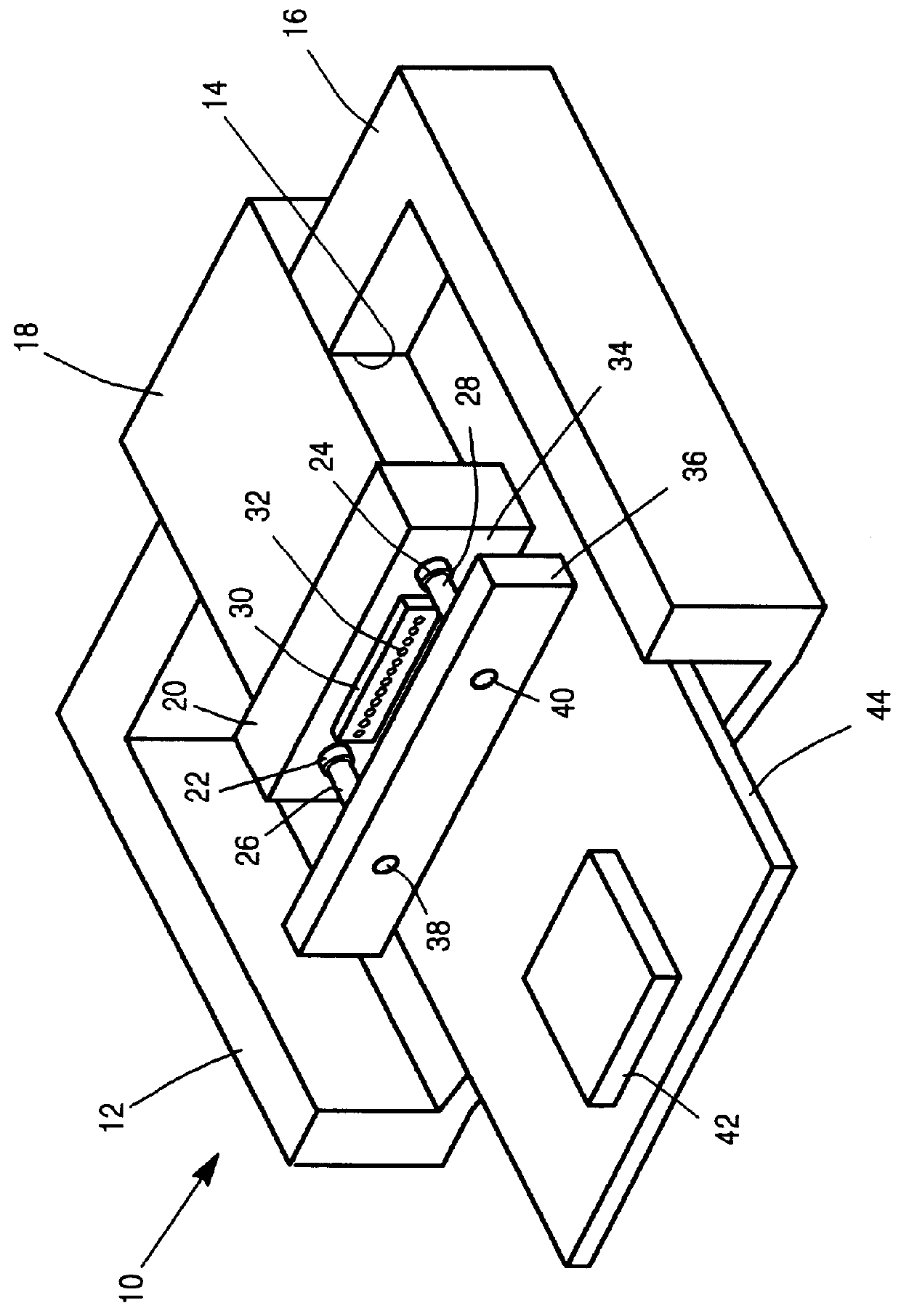
the invention is shown by reference to FIG. 1. The package 10 for the VCSEL laser array is enclosed in a housing 12 in which the top and the portion of the rear of the housing have been removed for clarity of illustration. An opening 14 is provided in the front wall 16 of the housing. This enables the insertion of a commercially available MT optical connector 18 into the opening 14 so that a substantial portion of the MT connector projects into the housing. The MT connector has an enlarged front block 20, which has a pair of blind holes 22, 24 into which the guide-pins 26 and 28, respectively, are inserted. The guide-pins ensure alignment between the optical input ports (not shown) of the optical connector that is located in the front block 20 and the optical elements that are optically coupled to each of these input ports.

The assembly 30 is an array of vertical cavity surface emitting lasers (VCSEL), which is positioned so that each of lasers 32 are aligned with a corresponding inp...


PUM


Abstract

A vertical cavity surface emitter array package for compiling optical data signals through an optical coupling connector is presented. The package includes the laser array that is mounted on a backing plate that has alignment holes in it, which receive alignment pins to align the array with the input end of the optical coupling connector. In one version of the package the input end of the optical coupling connector extends into the housing of the package and is aligned with the laser array. In a second version the optical coupling connector is extended to the housing and is aligned with optical fibers that project a feed-through assembly into alignment with a second optical coupling connector inside of the package, which in turn is aligned with the laser array. In a third embodiment an optical lens is aligned with the laser array and transmits optical data signals through a window insert in the housing of the package to the input end of the optical coupling connector.

Description

FIELD OF THE INVENTIONThis invention relates to optical array packaging for both vertical cavity, surface emitting, laser arrays and the corresponding photodiode detector array packaging.BACKGROUND OF THE INVENTIONVertical cavity, surface-emitting lasers (VCSEL), if properly packaged, can provide a cost effective laser array for the transmission of data signals. Prior laser array packages were often large in size, relatively expensive and required labor intensive active alignment. The present invention solves the above problems and allows optical transmitters to operate as high speed, parallel optical communication data links.SUMMARY OF THE INVENTIONAn optical data transmission package is provided that has a housing for transmitting optical signals that are generated inside of the housing of said package through an optical coupling connector that has an output end located externally of said housing and optical elements located internally of said housing. The package includes a print...

Claims


Application Information

Patent Timeline
Patent Type & Authority Patents(United States)
IPC IPC(8): G02B6/42G02B6/38
CPCG02B6/4292G02B6/4249G02B6/3861G02B6/4204G02B6/4238G02B6/4237
Inventor SAUTER, GERALD FRANCISSTEVENS, RICK CLEVIETHORSON, KEVIN JEROME
Owner THE UNITED STATES OF AMERICA AS REPRESENTED BY THE SECRETARY OF THE NAVY
Why Eureka
Try Eureka