Combination anti-skid anti-theft and vehicle lifting system

a vehicle and anti-theft technology, applied in the direction of anti-theft devices, anti-theft cycle devices, cycle equipments, etc., can solve the problems of vehicle owners' serious problems, vehicle theft is also a serious problem for vehicle owners, and the security system is expensiv

a vehicle and anti-theft technology, applied in the direction of anti-theft devices, anti-theft cycle devices, cycle equipments, etc., can solve the problems of vehicle owners' serious problems, vehicle theft is also a serious problem for vehicle owners, and the security system is expensiv

US6058749AInactive Publication Date: 2000-05-09REKEMEYER EDWARD

Image

  • Combination anti-skid anti-theft and vehicle lifting system
  • Combination anti-skid anti-theft and vehicle lifting system
  • Combination anti-skid anti-theft and vehicle lifting system

Examples


Embodiment Construction

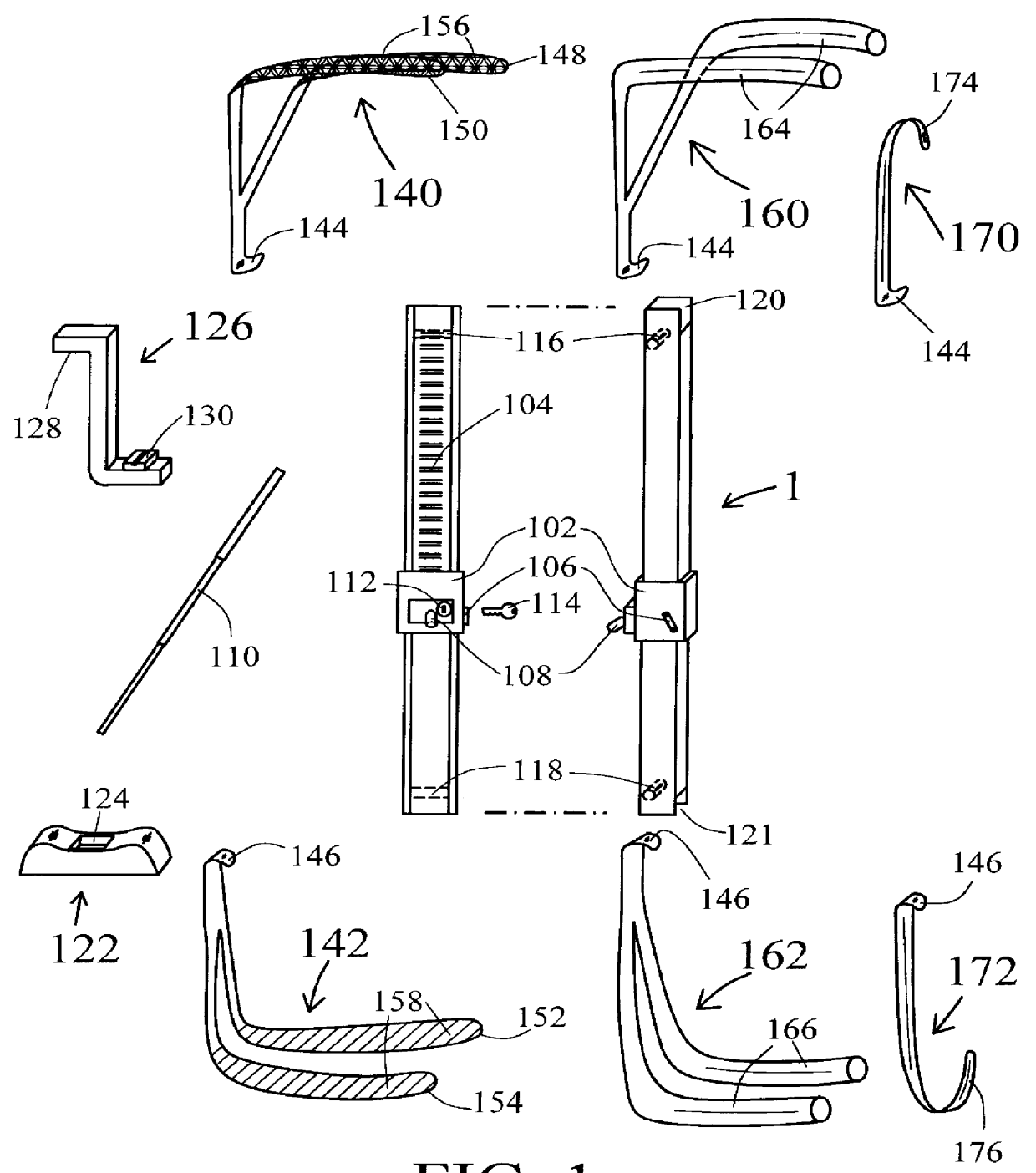
FIG. 1 depicts various required and optional components of the preferred embodiment of the invention, in a disassembled configuration, i.e., when these components are not yet connected together for the various uses (applications) as described below.

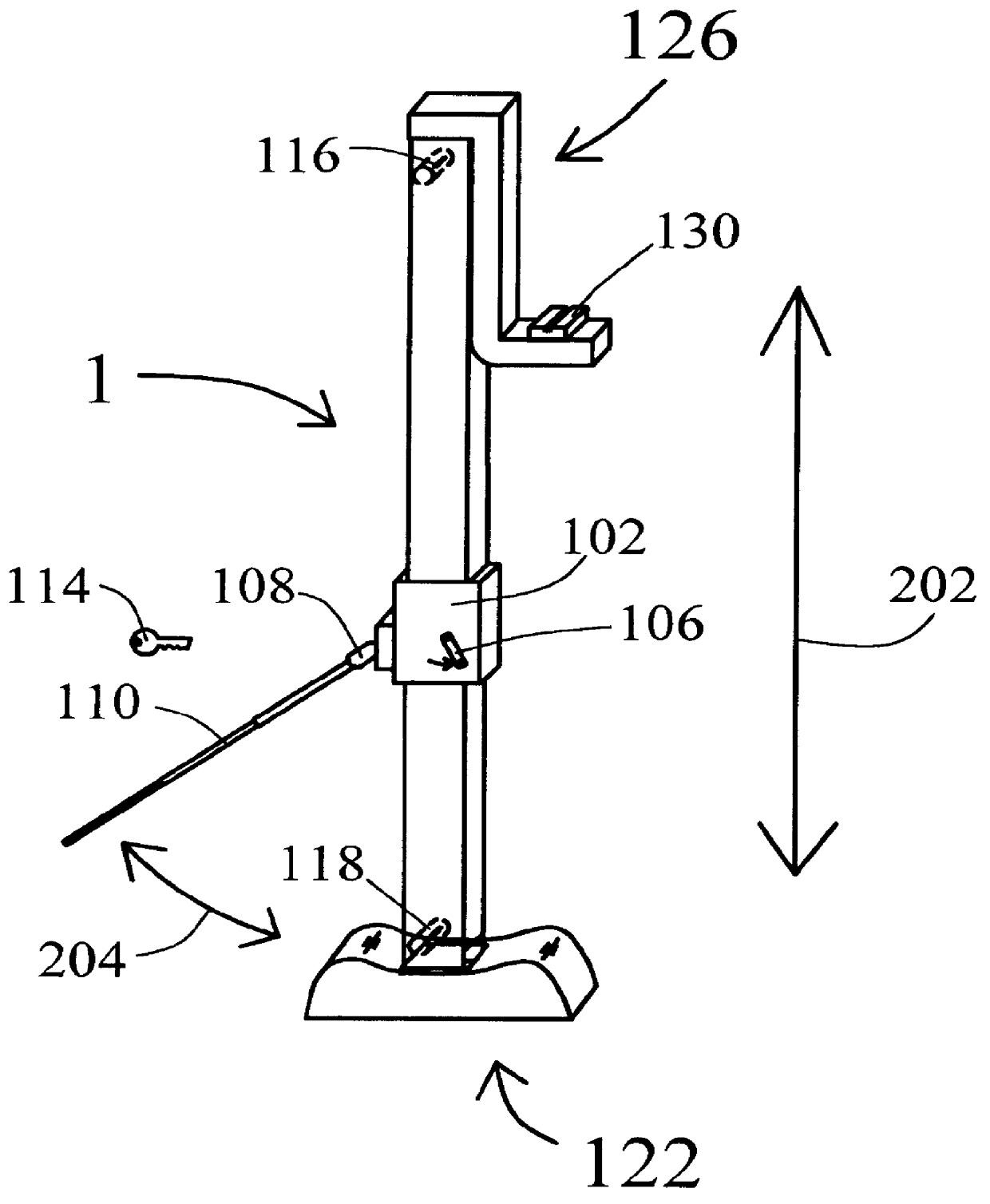
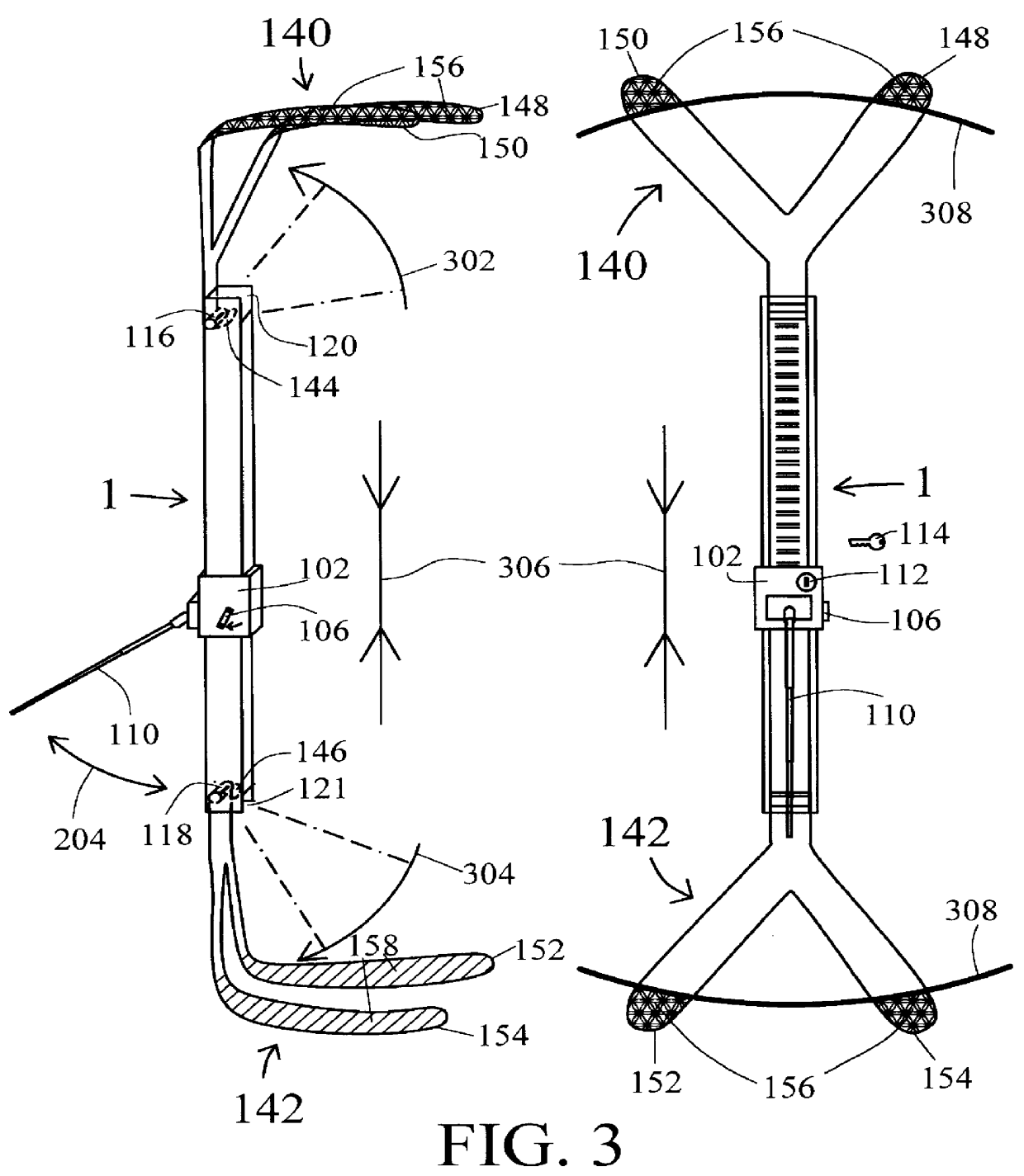
The primary component used for all of the varied applications to be discussed below is a reversible, bi-directional ratchet bar 1, depicted in FIG. 1 from both a front view and, projected therefrom, a predominantly right-side perspective view showing part of a rear view as well. This may be any ratchet bar known in the art that is capable of being reversibly switched to generate a force that either pushes apart or pulls together whatever is connected by or to the two ends of said ratchet bar 1.

One example of an acceptable embodiment for ratchet bar 1 is the ratchet bar component of a standard vehicle jack (vehicle jack bar), with reversibility, which is what is depicted in FIG. 1. The ratchet bar 1 comprises a drive mechanism 102, which o...


PUM


Abstract

Disclosed herein is a combination anti-skid, anti-theft and vehicle lifting device. In particular, the device disclosed herein attaches easily and quickly to a vehicle tire to help extract the tire and the vehicle to which it is attached from ice, mud, snow, or other immobilizing medium. It also converts readily to a conventional vehicle lifting jack for changing tires. It also converts readily to a "tire boot" and so can be used to prevent vehicle theft. Finally, it is readily convertible to as to immobilize the vehicle steering wheel, also for theft prevention.

Description

This invention relates generally to the field of utility tools for automotive vehicles, and in particular, discloses a multipurpose utility device that can be used to move a car stuck in ice or snow, which can secure the vehicle against theft, and which can also function as a traditional vehicle lifting jack.There exist today many tools for a motor vehicle owner that are use to provide assistance in a variety of difficult situations. The most common of these tools--a lifting jack--is used to lift a motor vehicle's tire off the ground in order to change such tire when it goes flat. Such jacks are indeed considered standard equipment for any motor vehicle, and are invariably provided by vehicle manufacturers with the purchase of a motor vehicle.While it is certainly annoying and trying to have to change one's tire when it becomes flat, getting stuck in ice, mud or snow can be equally difficult. Indeed, in cold-weather climates, having one's vehicle immobilized in ice or snow occurs ju...

Claims


Application Information

Patent Timeline
09 May 2000
Publication
US6058749A
IPC
B60R25/00; B60R25/02
CPC
B60R25/093; B60R25/0221; Y10T70/5889; Y10T70/40; Y10T70/5841; Y10T70/5836; Y10T70/5982
Inventors
REKEMEYER, EDWARD