Slide rail device for vehicle seat

a vehicle seat and rail technology, applied in the direction of roofs, movable seats, dismountable/non-movable seats, etc., can solve the problems of increasing the number of associated fittings and parts, increasing the weight of the seat, and requiring a number of additional assembling steps and man hours

Inactive Publication Date: 2000-05-09
TACHI S CO LTD
View PDF8 Cites 64 Cited by
  • Summary
  • Abstract
  • Description
  • Claims
  • Application Information

AI Technical Summary

Problems solved by technology

These hitherto structures of slide rail device, however, have been found defective in that its weight is increased and the number of associated fittings and parts are also increased, with a complicated designs incidental therewith, hence requiring a number of additional assembling steps and man hours.
Further, when the upper rail member are slid forwards and projected from the lower rail member, the forward set of rollers are exposed away from the lower rail member, in which case, the projected portion of upper rail member are fallen in contact with the bottom of lower rail member, interfering with the smooth forward sliding of the upper rail member along the lower rail member.
This contact also interferes with backward sliding of the upper rail member.
In that case, the exposed rollers collide with the forward edges of lower rail member, which prevents further backward sliding of upper rail member, with the result that the upper rail member can hardly be slid back to a home position upon the lower rail member.

Method used


Image

  • Slide rail device for vehicle seat
  • Slide rail device for vehicle seat
  • Slide rail device for vehicle seat

Examples


Embodiment Construction

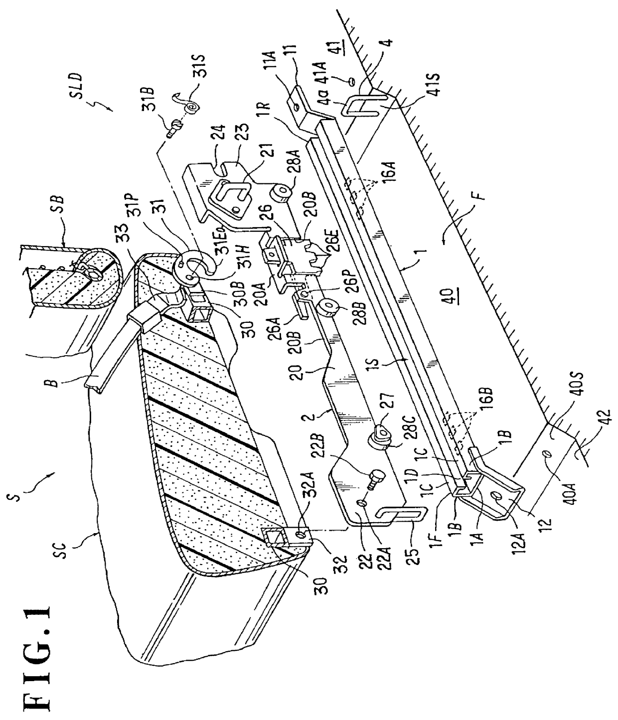
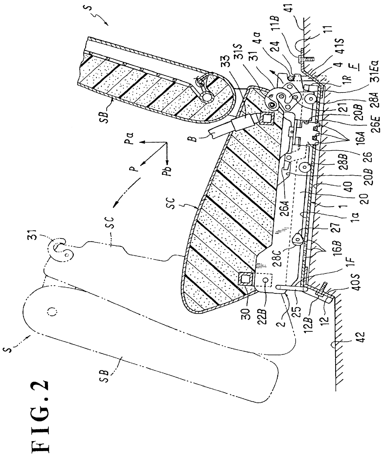
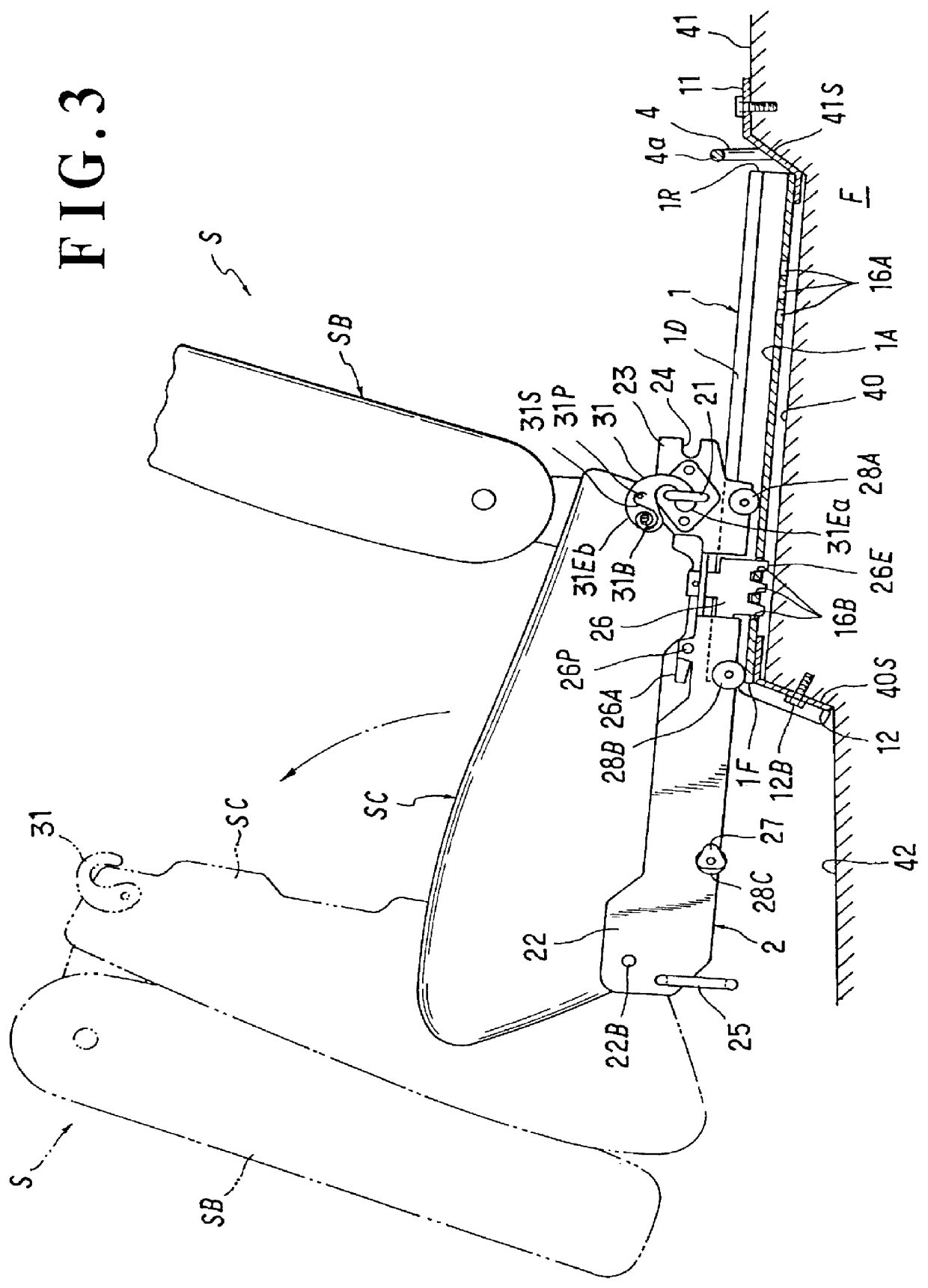
Referring to FIGS. 1 through 5, there is illustrated one exemplary embodiment of slide rail device in accordance with the present invention, which is applied to a jump-seat-type foldable vehicle or automotive seat as a combination relation therewith.

As shown by way of example in the figures, the slide rail device is generally designated by (SLD), whereas the automotive seat used in combination therewith is generally designated by (S). Insofar as shown in the present mode, the seat (S) is provided with a seat belt anchor (33) for lockable receipt of a buckle of seat belt (B) that serves to restrain the body of an occupant to the seat, and may be of known foldable type such that the seat back (SB) is foldable onto the seat cushion (SC). It should be understood that the slide rail device (SLD), as normally known in the art, assumes a pair of spaced-apart slide rails disposed underneath the seat cushion (SC) to support the seat (S) stable, and for the sake of simplicity, description and...


PUM


Abstract

A slide rail device for a vehicle seat including a lower rail member fixed on a floor of the vehicle and an upper rail member slidably fitted in the lower rail member. Basically, a stopper and a notch are provided respectively at the forward and rearward ends of the upper rail member, while a striker is provided at the floor of the vehicle, erecting therefrom. When the upper rail member is located at a home position upon the lower rail member, the stopper is abutted against the forward end of the upper rail member and side of the floor, with the notch being engaged over the striker, whereby the upper rail member is prevented against separation from the lower rail member. Another striker and hook-like lock member may be provided in the case where the vehicle seat is of a jump-seat type having a seat belt anchor, so that not only the seat is locked to the upper rail member against forward jumping, but also an upwardly slant pulling force applied through the seat belt anchor is dispersed and escaped to the floor through the stopper, two strikers, the lock member and the notch. Further, a guide roller arrangement is provided at the upper rail member for supportive sliding in the lower member, which includes a guide piece at one of the guide rollers that will be exposed from the lower rail member when the upper rail member is slid away from the lower rail member, such that the exposed portion of the upper rail member can be withdrawn into the lower rail member, with guiding aid of the guide piece.

Description

BACKGROUND OF INVENTION1. Field of the InventionThe present invention generally relates to a slide rail device for use in a vehicle seat such an automotive seat, which is operable to adjust the seat in position in the fore-and-aft direction. More specifically, the invention is directed to the slide rail device of this kind for particular use in a foldable type of vehicle seat provided with a seat belt anchor.2. Description of Prior ArtIn general, a slide rail device is provided for adjustment of fore-and-aft position of a vehicle or automotive seat. In the case where the slide rail device is applied to a vehicle seat of the kind having a seat belt anchor for anchoring a seat belt which restrains the body of an occupant to the seat, a structural reinforcement is arranged in the slide rail device to resist a great pulling force applied from the occupant through the seat belt in a collision case or the like. As a typical conventional arrangement in this regard, either of the upper and ...

Claims


Application Information

Patent Timeline
Patent Type & Authority Patents(United States)
IPC IPC(8): B60N2/30
CPCB60N2/3011B60N2/3093B60N2/305B60N2/06
Inventor YOKOTA, MASAAKI
Owner TACHI S CO LTD
Why Eureka
Try Eureka