Compact disk locking device

a technology of locking device and compact disc, which is applied in the direction of packaging goods, instruments, transportation and packaging, etc., can solve the problems of compact disc being damaged, compact disc being easily dropped, and compact disc being easily damaged

Inactive Publication Date: 2000-05-23
HOWERTON WILLIAM CASSIDAY +1
View PDF19 Cites 44 Cited by
  • Summary
  • Abstract
  • Description
  • Claims
  • Application Information

AI Technical Summary

Problems solved by technology

One of the problems with this common design of compact disc case is that the case can be dropped and the compact disc can be dislodged from the flexible, retaining ring.
When dislodged from the case, the compact disc will often be damaged.
Also, a compact disc can be damaged when it simply falls out of the case due to excessive wear of the flexible teeth that comprise the central retaining ring.
Still another problem with the common design is that small children that are able to reach the case can easily dislodge a compact disc from the flexible central retaining ring.
All of these problems stem from the fact that the flexible fingers that comprise the central retaining ring do not securely lock the compact disc to the disc seat.
Although a compact disc can be inserted onto the retaining ring without the user manually depressing the button, a compact disc can only be removed for the retaining ring by first depressing the button.
Also, because of the position of the button relative to a compact disc secured by the locking device, the locking device is essentially childproof.

Method used


Image

  • Compact disk locking device
  • Compact disk locking device
  • Compact disk locking device

Examples


Embodiment Construction

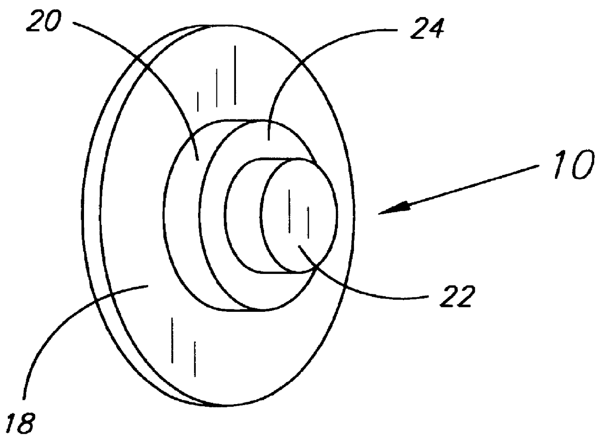
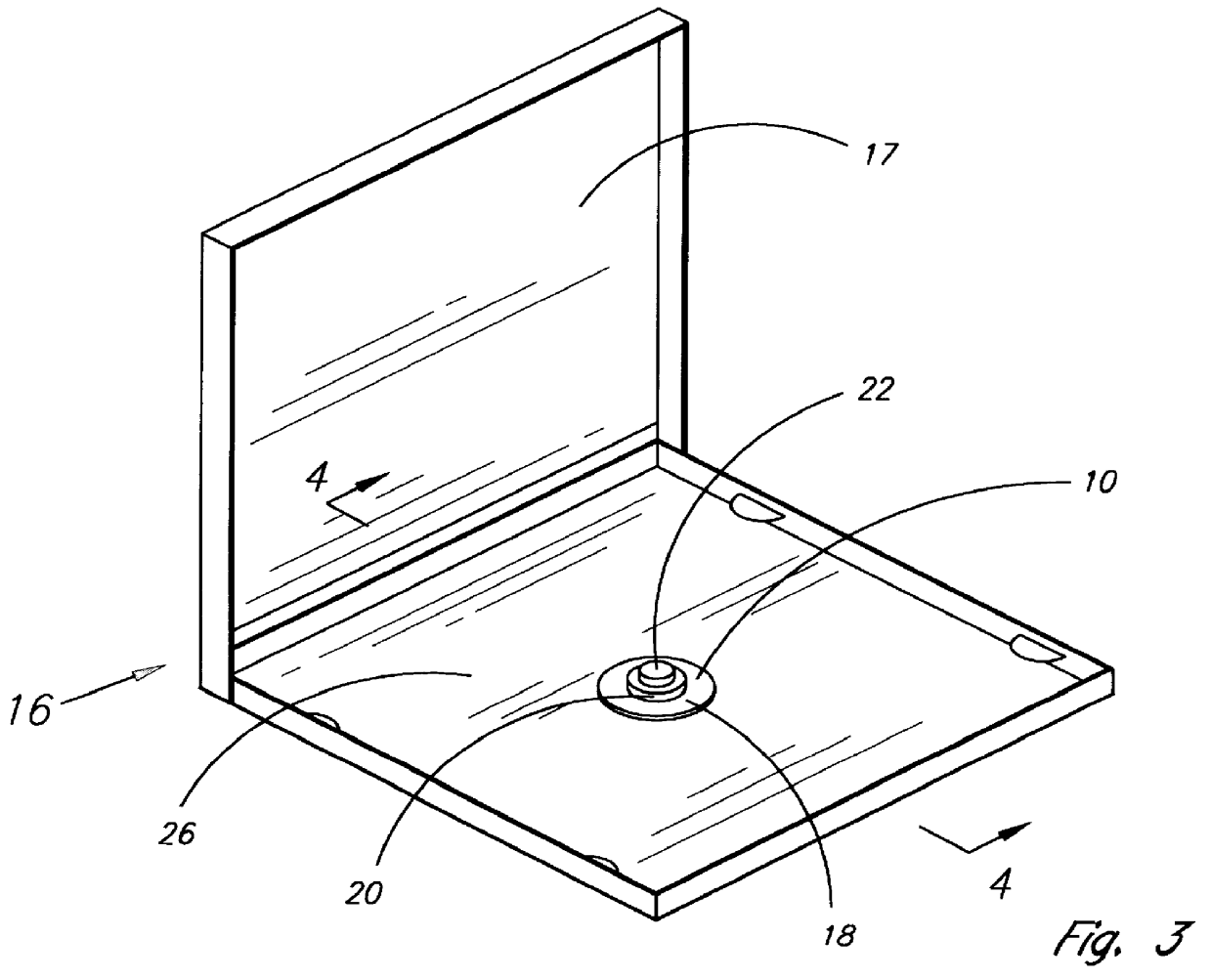
Referring now to the drawings and initially to FIGS. 1 and 3, there is illustrated a preferred embodiment of the present invention. The invention is a locking device 10 for releasable securing a compact disc 12 to a disc seat 14 that is provided in a compact disc case 16. The case 16, as illustrated in FIG. 3, normally consists of an articulating lid 17 and a bottom 26.

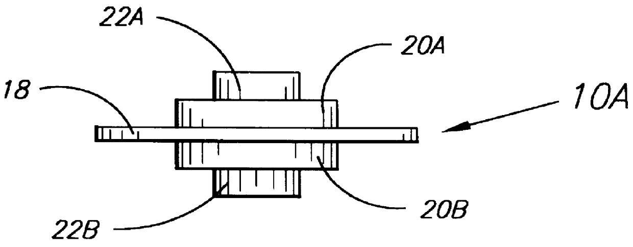
The device 10 is preferably made as one piece, having a flat base 18, a raised circular shoulder 20 and a raised button 22 located on the top 24 of the circular shoulder 20. In use, the device 10 is placed between the bottom 26 of the case 16 and the disc seat 14 so that the base 18 rests against the bottom 26 of the case 16. When the device 10 is thus installed, the circular shoulder 20 of the device 10 inserts into a middle 28 of a central retaining ring 30 that is provided on the disc seat 14. Also, when the device 10 is installed, the button 22 extends upward through the center opening 32 of the central retaining ...


PUM


Abstract

A locking device for releasable securing a compact disc to a disc seat provided in a compact disc case. The device has a flat base, a raised circular shoulder located on the base, and a raised button located on the top of the circular shoulder. The device inserts between the bottom of the case and the disc seat so that the base rests against the bottom of the case, the circular shoulder of the device removable inserts into the middle of the central retaining ring, and the button extends upward through the center opening of the central retaining ring. Although a compact disc can be inserted onto the disc seat without the user manually depressing the button, a compact disc can only be removed for the retaining disk seat by first depressing the button. Depressing the button presses the base against the bottom of the case, which flexes downward sufficiently to allow the shoulder of the device to move downward out of the middle of the central retaining ring, thereby unlocking the flexible teeth that comprise the central retaining ring so that a compact disc can be slipped over them.

Description

1. Field of the InventionThe present invention relates to a device that inserts into a compact disc case between the bottom of the case and the disc seat that secures a compact disc within the case. The present invention locks the compact disc to the disc seat so that the compact disc will not be accidentally removed from the disc seat.2. Description of the Related ArtCompact discs are sold to the public and are stored by the consumer in compact disc cases. These compact disc cases are normally constructed of high impact plastic. Compact disc cases are generally of a common design that employs a central retaining ring comprised of a plurality of flexible teeth for retaining a compact disc within the case. This central retaining ring is provided on a disc seat that secures to the bottom of the compact disc case. A hinged top that can be opened and closed is also provided on the compact disc case so that the bottom and top together form the thin compartment that houses the disc seat a...

Claims


Application Information

Patent Timeline
Patent Type & Authority Patents(United States)
IPC IPC(8): B65D85/57
CPCG11B33/045G11B33/0427
Inventor HOWERTON, WILLIAM CASSIDAYJOBE, DALE RAY
Owner HOWERTON WILLIAM CASSIDAY
Why Eureka
Try Eureka