Dispensing container with top and bottom access ports and a dispensing manifold therefore

a container and access port technology, applied in the direction of liquid transferring device, liquid handling, packaging goods type, etc., can solve the problems of not providing a flush mount hanging device, nor being able to be contained

Inactive Publication Date: 2000-05-23
SCOGGINS LESTER E
View PDF42 Cites 49 Cited by
  • Summary
  • Abstract
  • Description
  • Claims
  • Application Information

AI Technical Summary

Benefits of technology

It is a primary object of the present invention to provide a device as characterized above which provides a container with a female threaded opening at the bottom which can serve as a filler port when the container is placed upside down in its operative dispensing position. A supply container having a male thread compatible with the female thread of the dispensing container can be attached to the dispensing container and supported thereby in a vertical position to slowly empty its contents therein. This can be continued in series with additional bottles as designed. The openings can also be fitted with caps, pumps, valves or the like. A cap threaded onto a male threaded coupling on the opposite end from the filler port can seal or unseal the container as needed for disposing of fluid after filling.

Problems solved by technology

Nor does it provide a flush mounted hanging device.
Though even is hook does not provide for flush mounting, nor is it able to be contained within a liquid-fill opening.

Method used


Image

  • Dispensing container with top and bottom access ports and a dispensing manifold therefore
  • Dispensing container with top and bottom access ports and a dispensing manifold therefore
  • Dispensing container with top and bottom access ports and a dispensing manifold therefore

Examples


Embodiment Construction

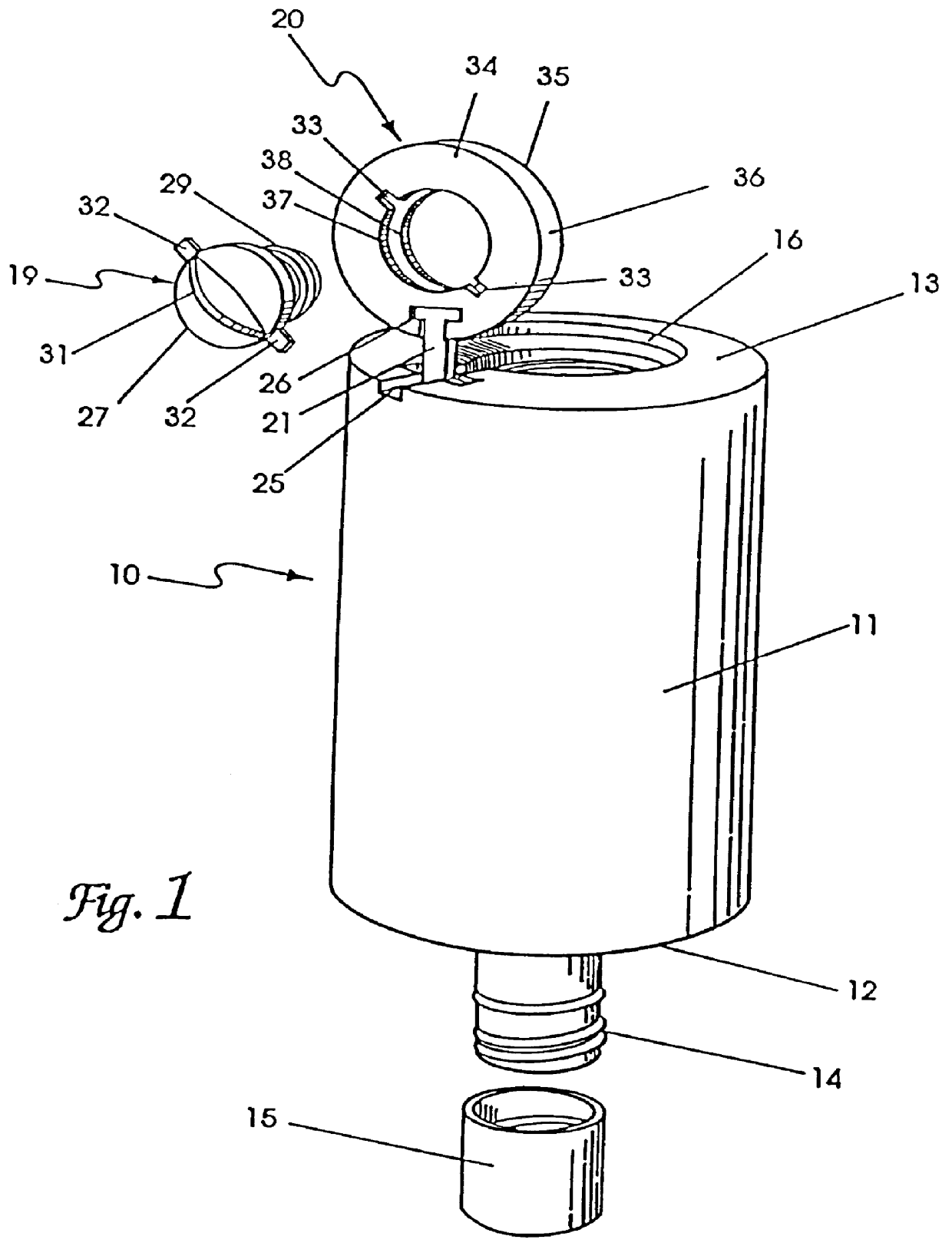
Considering the drawings, wherein like reference numerals denote like parts throughout the various drawing figures, reference numeral 10 is directed to the overall container according to the present invention. While the container of this invention can be tubular, parallel, piped or spherical in shape, it is preferred to employ a cylindrical container because of certain manufacturing simplifications and the ability of a cylindrical shape to contain a maximum volume. The invention will be described in terms of a cylindrical container, although it should be understood that other shapes can be employed.

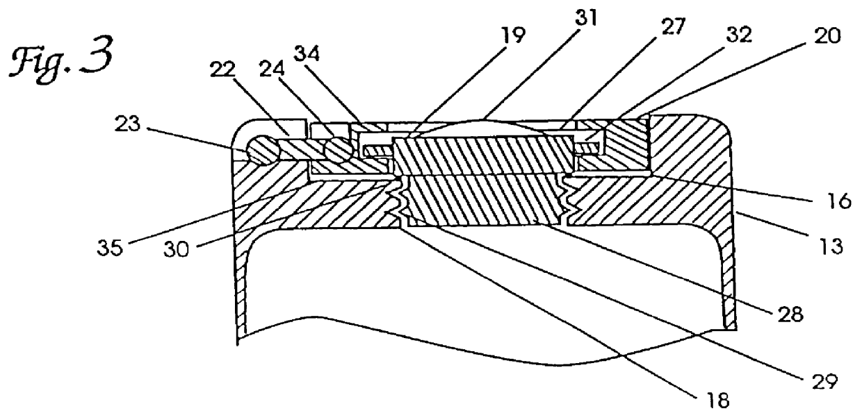
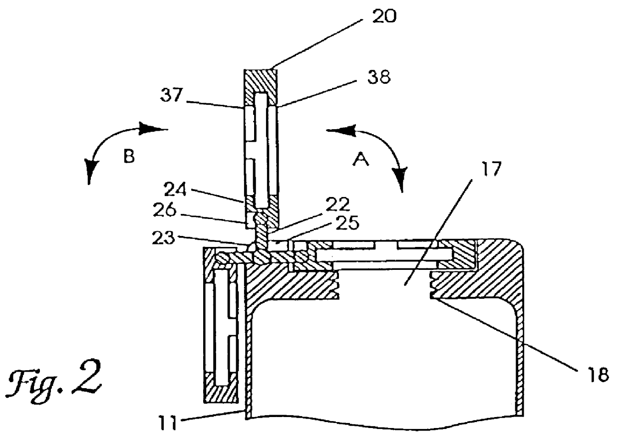
Referring now in particular to FIGS. 1 through 5, container 10 which is shown in an upside-down position for explanatory purposes, has a cylindrical body 11 with a generally flat top 12 and flat bottom 13. The flat top 12 is provided with a conventionally threaded container neck 14, preferably 24 mm or other industry standard diameter, which can be sealed with a matching threaded cap 15.

T...


PUM

PropertyMeasurementUnit
diameteraaaaaaaaaa
movementaaaaaaaaaa
diameteraaaaaaaaaa

Abstract

A dispensing container for viscous fluids formed of a tubular body having top and bottom surfaces with the top surface including a threaded outlet neck and the bottom surface including a recessed portion with a female threaded opening. The container is designed to operate in an upside-down manner to take advantage of gravity flow. A hanger ring is provided which pivots out of the recessed portion to suspend the container in an upside-down position. A plurality of bottles can be vertically supported by a dispensing manifold to yield different dispensing relationships.

Description

This invention relates to fluid containers having top and bottom openings to gain access to the interior. This invention also relates to manifolds for dispensing fluids from a container such as that described above.The following prior art reflects the state of the art of which applicant is aware and is included herewith to discharge applicant's acknowledged duty to disclose relevant prior art. It is stipulated, however, that none of these references teach singly nor render obvious when considered in any conceivable combination the nexus of the instant invention as disclosed in greater detail hereinafter and as particularly claimed.U.S. Pat. No. 3,071,281 discloses a tubular container provided with threaded neck at each end which can be sealed with a threaded cap. The interior of the container can be accessed from either end. However, those ends are not complimentary formed, among other short-comings vis-a-vis the invention at issue.U.S. Pat. No. 4,085,867 discloses a dispensing syst...

Claims


Application Information

Patent Timeline
Patent Type & Authority Patents(United States)
IPC IPC(8): A47K5/00A47K5/12B65D71/50B65D23/00B65D1/06B67D3/00
CPCA47K5/1214B65D1/06B65D71/502B67D3/00B65D23/003B67D2210/00131
Inventor SCOGGINS, LESTER E.
Owner SCOGGINS LESTER E
Why Eureka
Try Eureka