Unitary concrete pumping station for aqueous waste submersible pumping applications

a technology of unitary concrete and submerged pumping, which is applied in the direction of service pipe systems, machines/engines, liquid fuel engines, etc., can solve the problems of affecting the installation efficiency of the system, and reducing the time required for installation. , to achieve the effect of improving the installation of the system and reducing the time required for installation

Inactive Publication Date: 2006-12-19
ELECTRIC TECH
View PDF6 Cites 29 Cited by
  • Summary
  • Abstract
  • Description
  • Claims
  • Application Information

AI Technical Summary

Benefits of technology

[0008]There is a pressing need or object within the prior art for a unitary pumping station for pumping aqueous waste or storm materials from one level to another. There is also a pressing need or object within the prior art for a pumping station that can be installed without fear of breakage when the disturbed ground moves after installation. Finally, there is also a pressing need or object for a pumping station that can be manufactured usually in a single pieces with the requisite parts and elements already installed and so as to permit joining of these pieces, especially in larger systems, of chambers right on the site. There is also a need to provide smaller systems that can be entirely manufactured away from the installation site and thus improve installation thereof. This will reduce the time requisite for installation thereof. Also, there is a pressing need to have a secure and safe pumping station that can be installed underground in streets and the like and that will survive vehicular traffic that passes overhead. These and yet other objects are achieved in a unitary cementitious pumping station for moving aqueous waste materials from one level to another comprising in order,

Problems solved by technology

It is difficult, however, to provide a total gravity flow system and it is sometimes necessary to have one or more pumping stations within the waste handling flow areas in order to move the waste stream along to its ultimate destination.
There are some serious problems with current pumping stations within the prior art.
Since the ground must be disturbed during the installation of these two points there is a tendency for the disturbed ground to settle and this settling causes movement of the piping between the collection point and the valve chamber and occasionally a line break occurs.
This line breakage is a serious event and it is always necessitates the need to excavate the area around and between the two points in order to get to the line for repair.
This is a very costly step and when there are several such pumping stations and several such line breaks the costs elevate considerable.
Additionally, any leaks that may occur around these pumping stations can result in ground water pollution.
Most of the current pumping stations are not suitable for installation under streets and the like since they must survive the constant flow of vehicular traffic without cracking lines and the like.
There is also considerable installation costs incurred by using these prior art pumping stations.
Considerable ground must be excavated and putting together the two chambers or containers is time consuming and sometimes dangerous.
As mentioned previously, it is difficult to sufficiently compact the ground around the containers and thus the shifting and / or settlement problems occur as previously mentioned.
The two or more container system is also complicated requiring a great deal of skill to construct.
Also, since the valve chamber or container is smaller in size it tends to “float” and / or “sink” in the disturbed ground area causing additional strain such as shears and breaks on the piping system.
Finally, since the two container or chamber system is more complicated, the construction of pumping stations using these prior art systems is also very complicated and requires a lot of individual parts.
Thus, the installer must have on hand a great variety of elements and this is very expensive.

Method used


Image

  • Unitary concrete pumping station for aqueous waste submersible pumping applications
  • Unitary concrete pumping station for aqueous waste submersible pumping applications
  • Unitary concrete pumping station for aqueous waste submersible pumping applications

Examples


Embodiment Construction

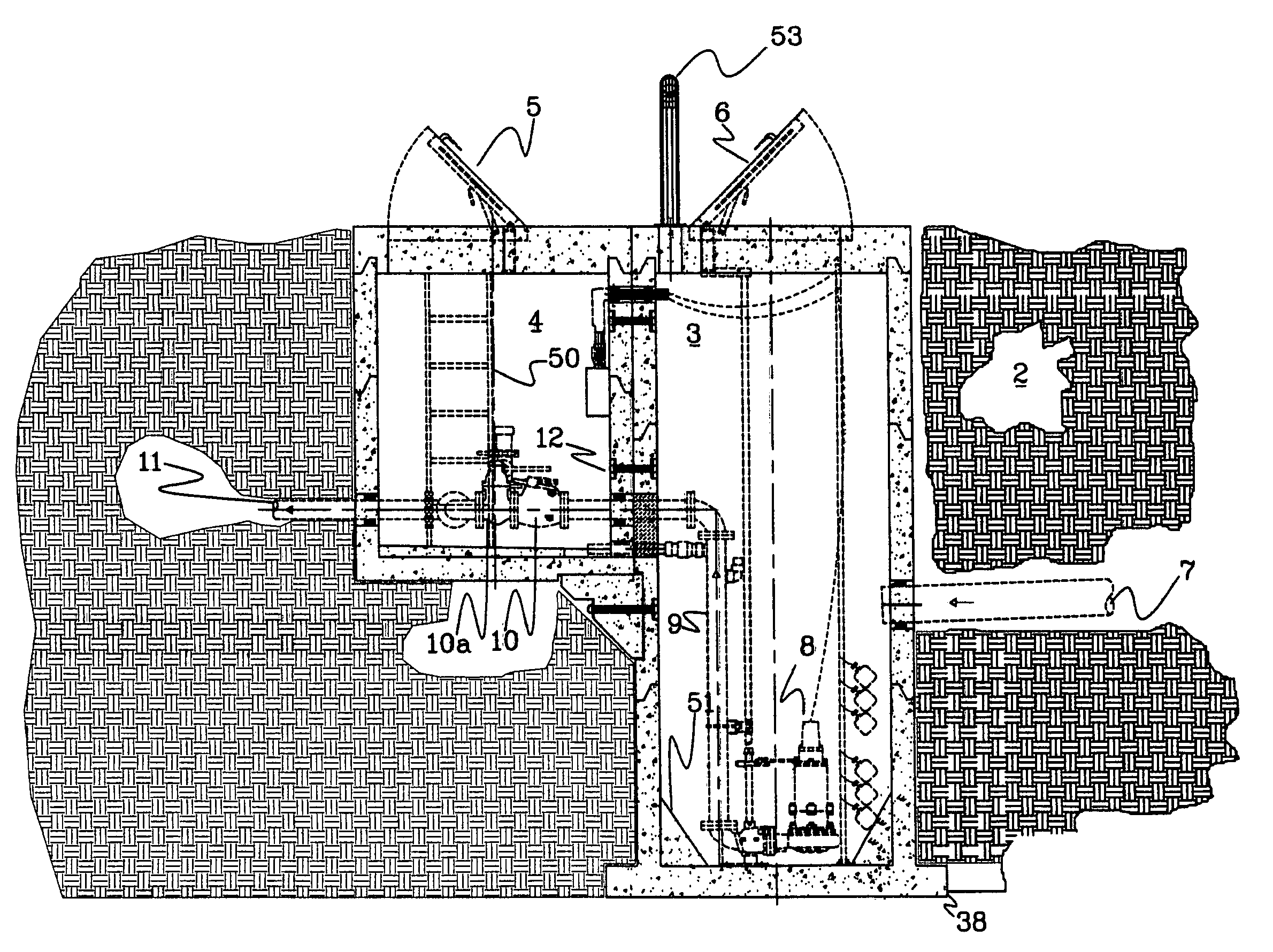
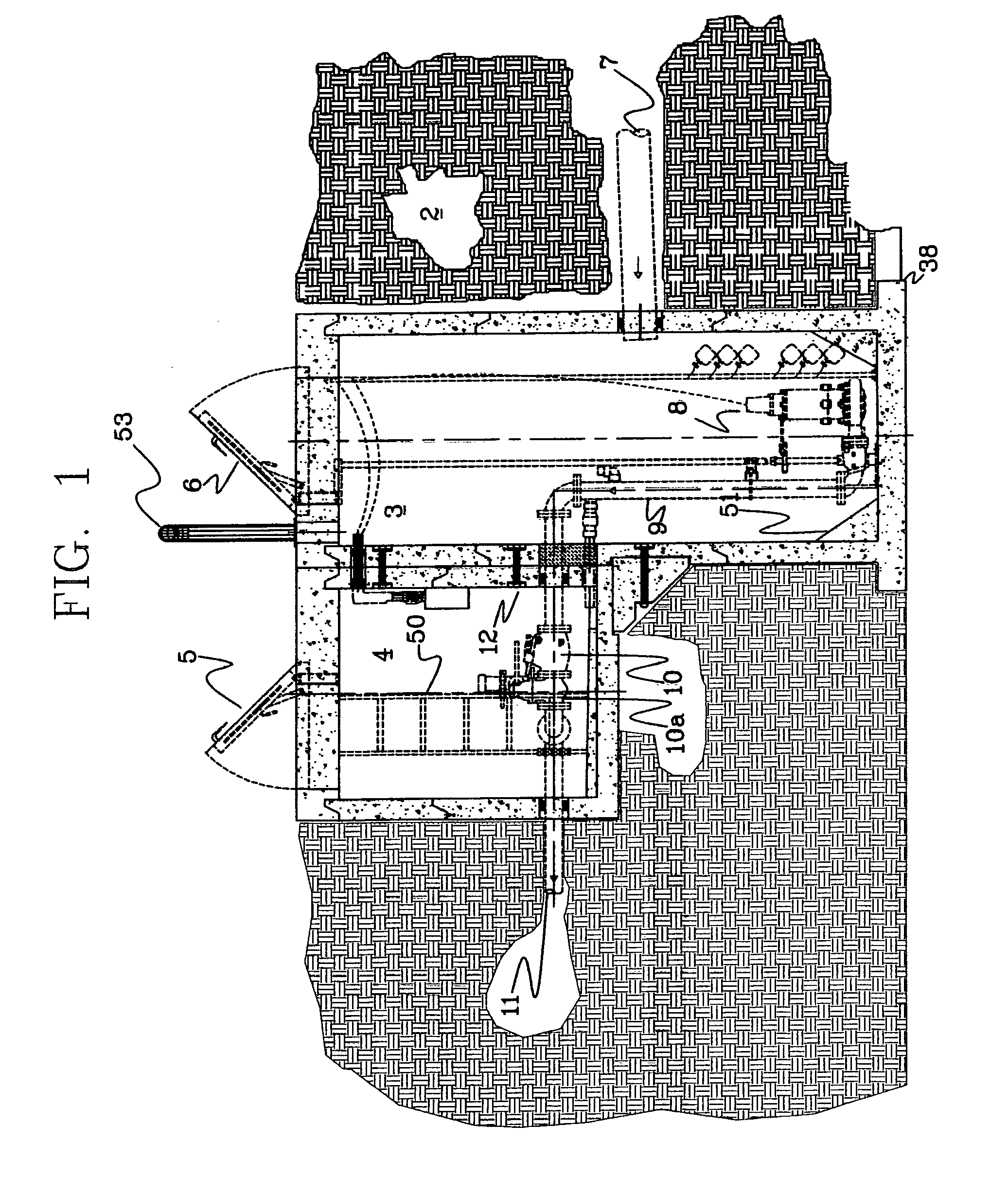
[0021]Looking now specifically at the drawings particularly useful in describing this invention, but by which I am not limited, FIG. 1 is a basic and simple form of the unitary pumping station useful in moving waste fluids from one level to another. In this showing 1 is the unitary pumping station as a whole shown beneath the ground 2. A squared, fluid receiving container is shown as 3 and a smaller, squared valve container shown as 4. Each of these two containers may have a man-hole access point as shown as 5 and 6. In the fluid receiving container the fluid enters in at a certain level through inlet pipe 7. As the fluid rises up in this container a submersible pump 8 pumps this fluid up into the smaller valve container 4 through a pipe 9. This fluid passes through an integral check valve 10 and then through a gate valve 10a and exits through pipe 11 further into the system. The entire system is a unitary pumping station with fluid entering at a lower level and being pumped into a ...


PUM


Abstract

A unitary concrete structure pumping station useful in pumping waste fluids and the like during the passing of such materials from one part of a gravity flow waste system to another. This concrete structure is simple to install and use and many of the problems associated with conventional pumping stations are alleviated. The structure is comprised of several parts that can be made pre-assembled at the factory or assembled in the field prior to installation. By being a unitary structure this pumping station is resistant to movements within the earth and therefore less likely to incur line breaks.

Description

BACKGROUND OF THE INVENTION[0001]1. Field of the Invention[0002]This invention relates to the fields of waste and storm water pumping and waste product management and more particularly to the means of pumping such waste materials into a pressurized pipe and further on into a gravity sewer waste handling system for further treatment and processing. More particularly, this invention relates to gravity flow waste handling systems. Still more particularly, this invention relates to an improved pumping stations for such waste handling and to a unitary structure employed as a system with submersible pumping systems or pump stations. Even more particularly, this invention relates to pumping stations that can be installed within the flow and area of vehicular traffic.[0003]2. Description of the Prior Art[0004]Most commercial waste handling systems usually employ some sort of gravity flow to carry the waste along a piping system and subsequently to treatment or other handling systems. Many o...

Claims


Application Information

Patent Timeline
Patent Type & Authority Patents(United States)
IPC IPC(8): F16L5/00E02D29/14
CPCE03F5/22F04D29/606Y10T137/86356Y10T137/7025Y10T137/86163Y10T137/86228Y10T137/6991Y10T137/402
Inventor SMITH, FRANK J.
Owner ELECTRIC TECH
Why Eureka
Try Eureka