Headlight with a twin filament lamp for producing a chopped beam and an unchopped beam

Inactive Publication Date: 2000-05-30
VALEO VISION SA
View PDF11 Cites 13 Cited by
  • Summary
  • Abstract
  • Description
  • Claims
  • Application Information

AI Technical Summary

Benefits of technology

Preferably, the central sub-zone of the first zone of the reflector provides a greater lateral spread of the light than that pr

Problems solved by technology

This is explained by the fact that the base surfaces from which the various reflectors are made differ quite radically from each other, and the use of a common mould cavity would lead to major variations in thickness of the reflector, leading to high consumption of moulding material and to risks of mechanical instability at high temperatures.
However, the disclosures in that European patent document do not enable a headlight with both main beam and dipped beam facilities to be made with the same advantages.

Method used


Image

  • Headlight with a twin filament lamp for producing a chopped beam and an unchopped beam
  • Headlight with a twin filament lamp for producing a chopped beam and an unchopped beam
  • Headlight with a twin filament lamp for producing a chopped beam and an unchopped beam

Examples


Embodiment Construction

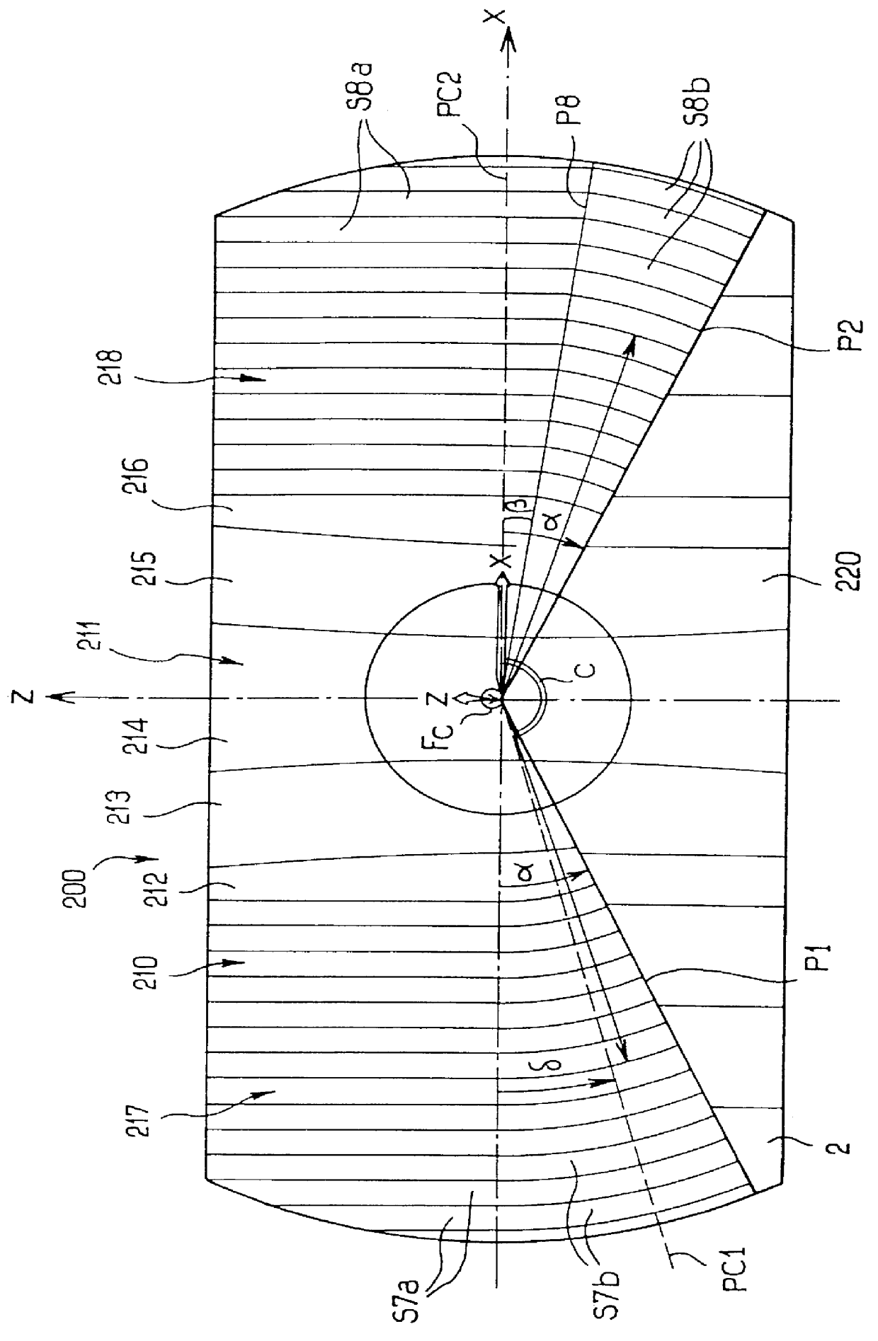
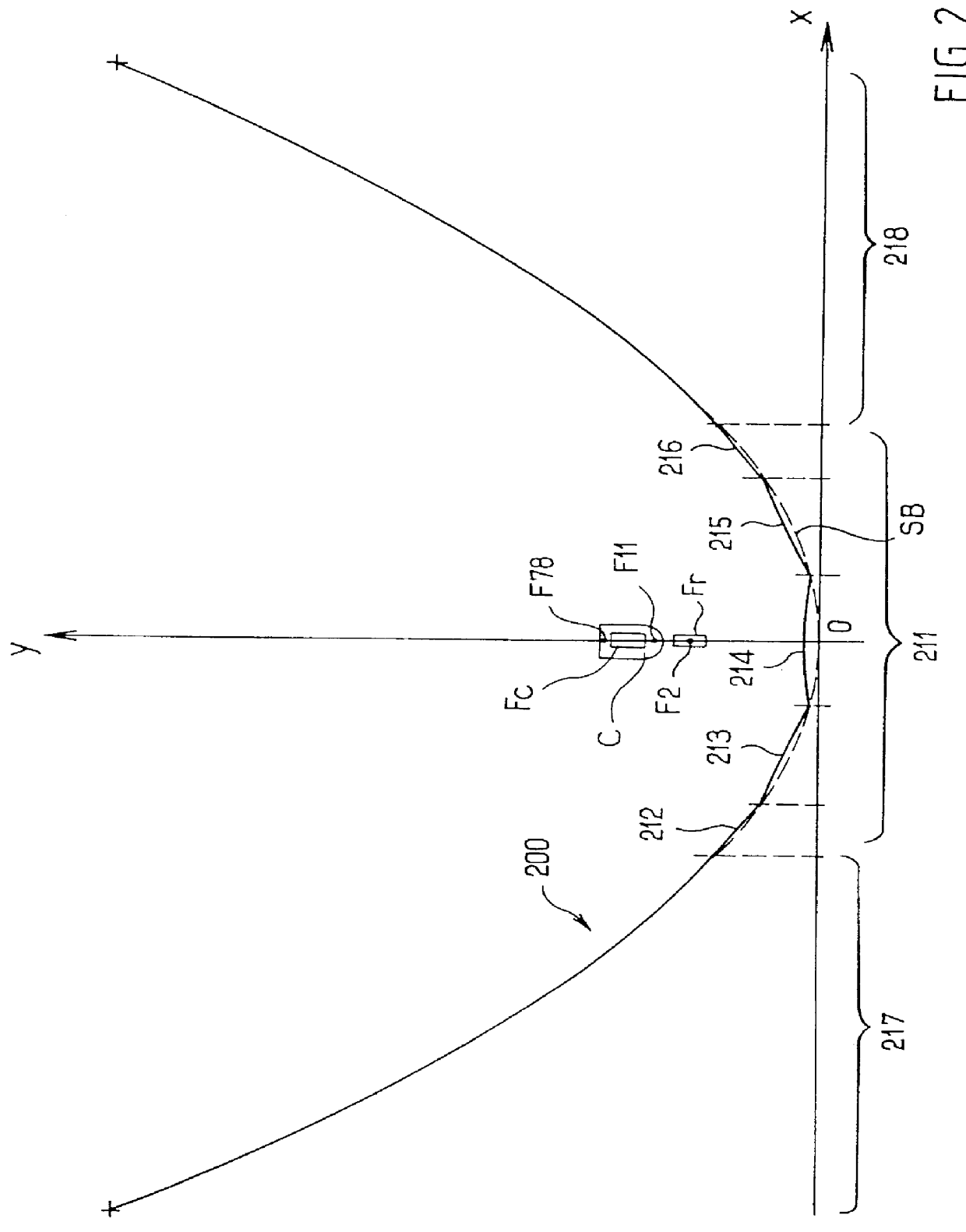
Reference is first made to FIGS. 1 and 2, showing a headlight reflector 200 in which a twin filament lamp is mounted. One of the filaments is a dipped beam filament and is provided with a masking screen. In this example, the lamp is an "H4" normalised lamp, in which the first, or dipped beam filament is denoted Fc and is associated with the masking screen C. The second filament is a main beam filament Fr, which is arranged behind the dipped beam filament and slightly offset downwardly from the latter. No masking screen is associated with the filament Fr.

A lamp of this kind is normally arranged to cooperate with a reflector of generally parabolic form, the focus of which lies somewhere between the filaments. The shape of the masking screen, which extends over approximately 165.degree. around the dipped beam filament Fc, and below the latter, defines a normalised European V-shaped cut-off, with a cut-off elevation angle .delta., typically of 15.degree., which is in the right hand half...


PUM


Abstract

A motor vehicle headlamp has a lamp with two filaments, one of which has a masking screen so as to form a chopped or dipped beam, while the other filament is unmasked so as to produce an unchopped beam. The headlight also includes a reflector and a smooth cover lens. The reflector has an upper zone extending between two radial half planes which are inclined by the same amount below the horizontal, this upper zone being larger than the part of the reflector which is exposed to the first filament; the reflector has two lateral sub-zones with base surfaces which are symmetrical with respect to the vertical, with striations being formed by projection on the base surface, the striations being configured according to the particular type of chopped beam required. The reflector also has a second zone having a surface for cooperation with the second filament only, so as to form a wide portion of the beam and extending at least partly above the cut-off of the dipped beam.

Description

The present invention relates in general terms to motor vehicle headlights. More particularly, the invention relates to a headlight with a light source having two filaments, which are typically incorporated in a single lamp, and in which one of the filaments is associated with means for restricting the field of illumination given by that filament, typically in the form of a masking screen. This mask restricts the field of emission of light from this first filament by the headlight. The beam emitted by the headlight from this second filament is therefore a chopped beam, which may typically consist of a dipped beam but which may be selected among various types of chopped beam. The other filament has no masking means, and produces an unchopped beam such as a headlight main beam.Such a light source, such as a lamp, is generally associated with a parabolic reflector, the focus of which is located between the two filaments of the lamp. The headlight further includes a cover lens which has...

Claims


Application Information

Patent Timeline
IPC IPC(8): F21V7/00F21S8/10B60Q1/076F21V14/02F21V14/08
CPCF21S48/1172F21S48/171F21S48/1376F21S48/1364F21S41/164F21S41/335F21S41/337F21S41/62
Inventor SALADIN, DENISBREL, JEAN-MARIE
Owner VALEO VISION SA
Why Eureka
Try Eureka