Vehicle headlamp

a headlamp and vehicle technology, applied in the field of vehicle headlamps, can solve the problems of increasing the number of lamp units required for a vehicle headlamp, and achieve the effects of preventing the formation of an unilluminated zone, and reducing the number of components

Active Publication Date: 2007-01-02
KOITO MFG CO LTD
View PDF4 Cites 80 Cited by
  • Summary
  • Abstract
  • Description
  • Claims
  • Application Information

AI Technical Summary

Benefits of technology

[0009]The present invention has been conceived in view of the above circumstances and provides a vehicle headlamp configured to form light distribution patterns by light radiation from lamp units which employ semiconductor light-emitting elements as light sources. The lamp unit enables formation of a low-beam light distribution pattern having sharp cut-off lines at an upper end portion and ensures a desired brightness while suppressing the number of lamp units to be disposed.

Problems solved by technology

However, when a lamp unit for low-beam and a lamp unit for high-beam are configured independently, there arises a related art problem that a number of lamp units required for a vehicle headlamp becomes considerably large.

Method used


Image

  • Vehicle headlamp
  • Vehicle headlamp
  • Vehicle headlamp

Examples


second embodiment

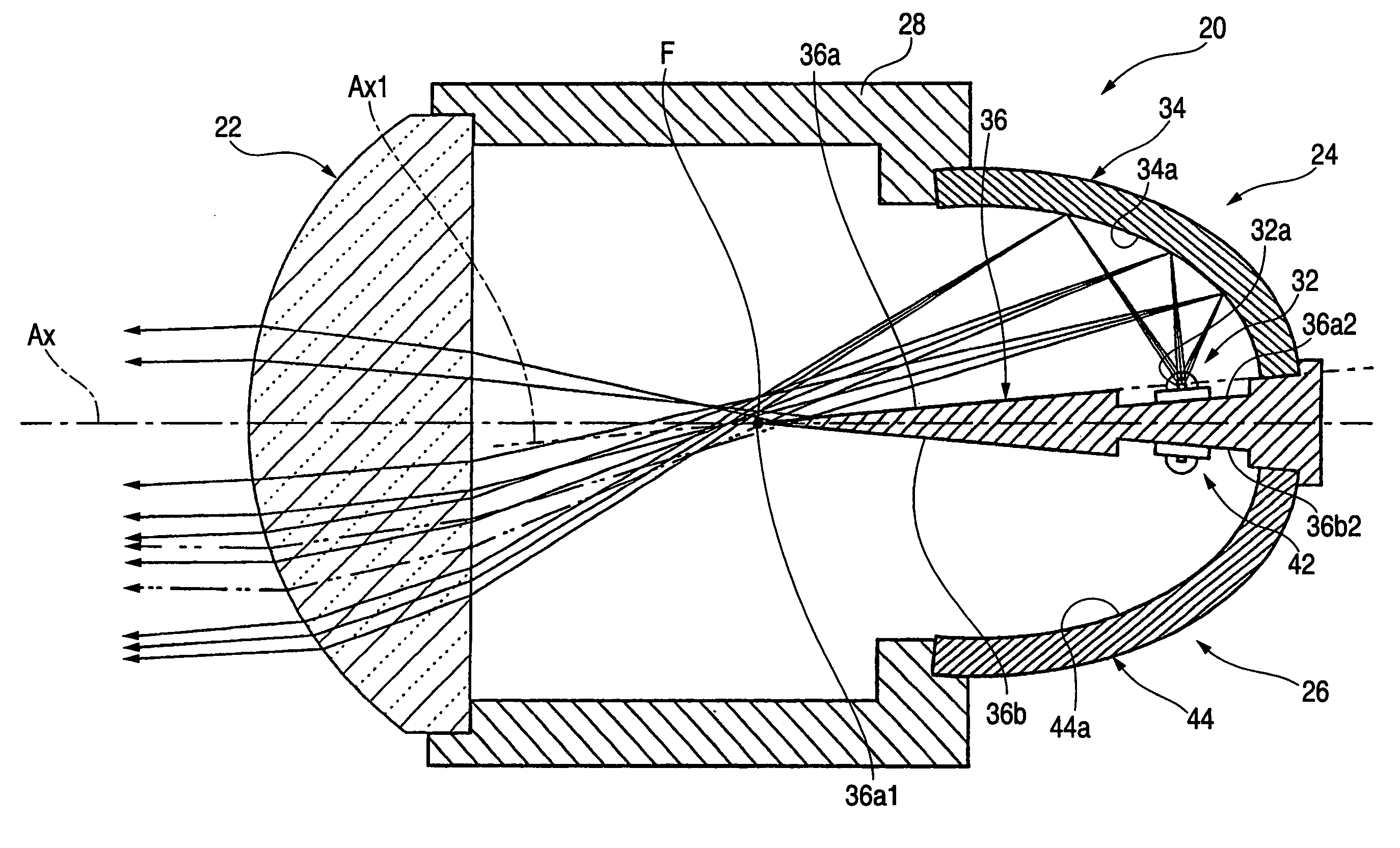
[0074]Next, a second exemplary, non-limiting embodiment of the present invention will be described. FIGS. 8 and 9 are views, which are analogous to FIGS. 4 and 5, showing a lamp unit 120 of the The lamp unit 120 comprises, as in the case with the lamp unit 20 of the embodiment, a projection lens 122, a first light-source unit 124 and a second light-source unit 126 which are disposed to the rear of the projection lens 122, and a cylindrical holder 128. The cylindrical holder 128 connects the projection lens 122, the first light-source unit 124, and a second light-source unit 126. However, specific configurations of the respective elements differ from those of the aforementioned first exemplary, non-limiting embodiment of the present invention.

[0075]As shown in FIG. 8, the first light-source unit 124 comprises a first semiconductor light-emitting element 132 and a first translucent block 134. The first reference axis Ax1 of the first light-source unit 124 extends coaxially with the o...

first embodiment

[0077]The first translucent block 134 is made of a transparent molded plastic formed to seal the first semiconductor light-emitting element 132 and the substrate 136 from above. The first translucent block 134 provides similar functions of light distribution to that of the first reflector 34 and the forward travel blocking member 36 of the

[0078]More specifically, reflection surface treatment such as aluminum deposition is applied on an upper surface 134a of the first translucent block 134 except for a region near a front end thereof. Accordingly, there is configured a reflection surface 134c which reflects light from the first semiconductor light-emitting element 132 forward and close to the first reference axis Ax1, thereby substantially converging the reflected light to a point in the vicinity of the rear focal point F (more specifically, a point slightly forward of the rear focal point F) of the projection lens 122.

[0079]An underside surface 134b of the first translucent block 13...


PUM


Abstract

A vehicle headlamp includes a projector-type lamp unit that performs two types of light distribution. The lamp unit is configured with a projection lens disposed on an optical axis Ax extending in an longitudinal direction of a vehicle, and a first light-source unit and a second light-source unit, both disposed to the rear of the projection lens. A low-beam light distribution pattern having sharp cut-off lines at an upper end portion is formed upon illumination of the first light-source unit. An additional high-beam light distribution pattern spreading upward from the cut-off lines is additionally formed upon illumination of the second light-source unit. Accordingly, a high-beam light distribution pattern is formed.

Description

[0001]This application claims foreign priority from Japanese Patent Application No. 2003-338448, filed on Sep. 29, 2003, the contents of which is incorporated herein by reference in its entirety.BACKGROUND OF THE INVENTION[0002]1. Technical Field[0003]The present invention relates to a vehicle headlamp which is configured to form light distribution patterns by light radiation from lamp units which employ semiconductor light-emitting elements as light sources.[0004]2. Related Art[0005]As described in JP-A-2003-123517, a related art vehicle lamp including a plurality of lamp units that employ semiconductor light emitting elements as light sources has been conventionally known.[0006]A related art vehicle headlamp is generally configured to allow switching between a low-beam and a high-beam. A low-beam light distribution pattern having sharp cut-off lines at an upper end portion can be formed when a so-called projector-type lamp unit is employed as the lamp unit, and a light-shielding m...

Claims


Application Information

Patent Timeline
Patent Type & Authority Patents(United States)
IPC IPC(8): B60Q1/064B60Q1/14F21S8/10F21S8/12F21V7/00F21V11/16F21V13/14F21V14/02F21V14/08F21W101/10F21Y101/02
CPCB60Q1/14F21S48/1159F21S48/1163F21S48/1241F21S48/145F21Y2101/02F21V7/0008F21V7/0091F21V13/14F21Y2115/10F21S41/147F21S41/155F21S41/24F21S41/43F21S41/663F21S41/148F21S41/151F21S41/322
Inventor ISHIDA, HIROYUKI
Owner KOITO MFG CO LTD
Why Eureka
Try Eureka