
Automotive discharge bulb and automotive headlamp

a technology for automotive headlamps and discharge bulbs, which is applied in the direction of discharge tubes luminescnet screens, fixed installations, lighting and heating apparatus, etc., can solve the problems of blackening and devitification phenomena, no appropriate light distribution, and problems such as related art discharge bulbs, so as to reduce the proportion of wasteful consumed light

Inactive Publication Date: 2005-01-13
KOITO MFG CO LTD
View PDF3 Cites 82 Cited by
  • Summary
  • Abstract
  • Description
  • Claims
  • Application Information

AI Technical Summary

Benefits of technology

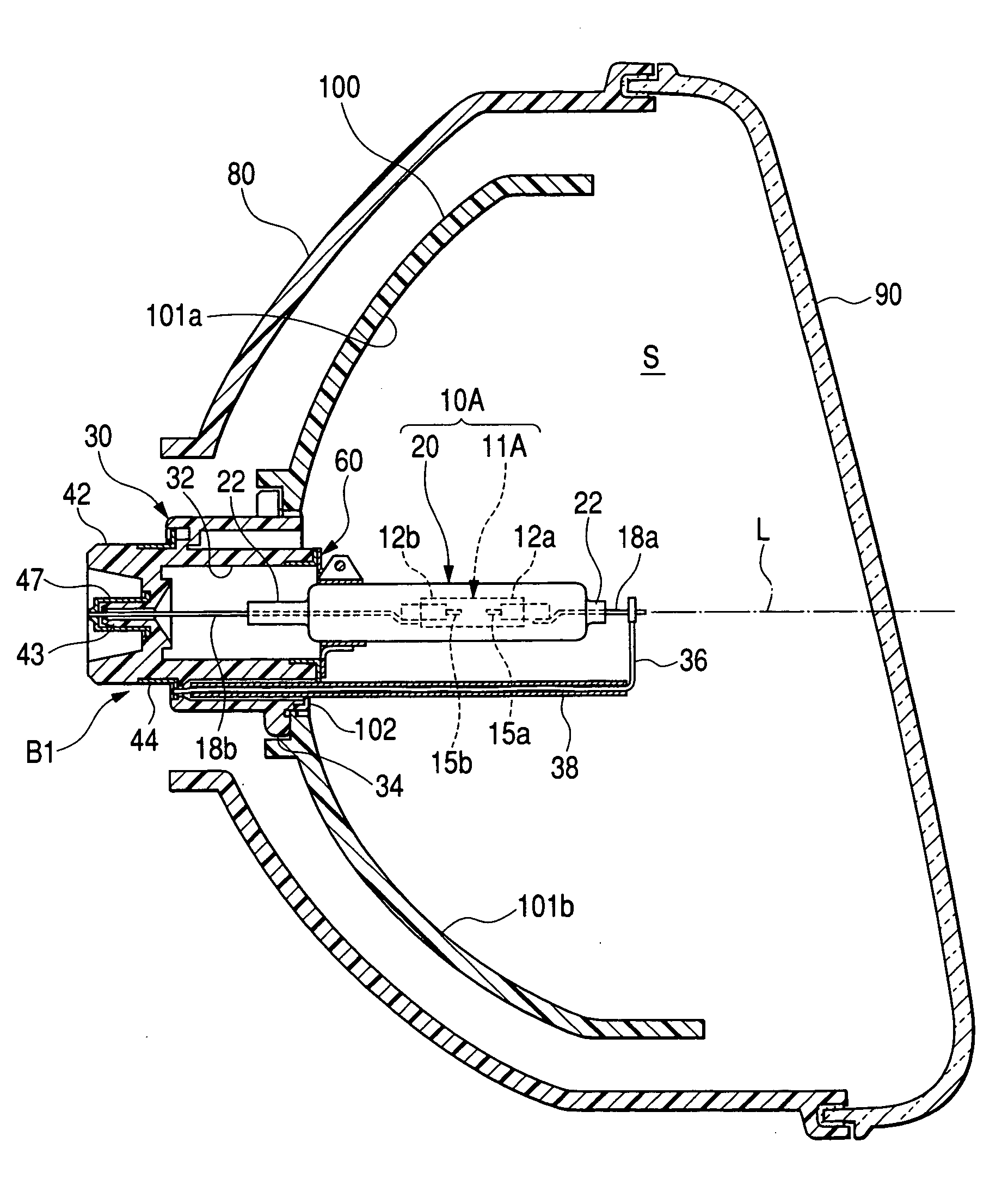
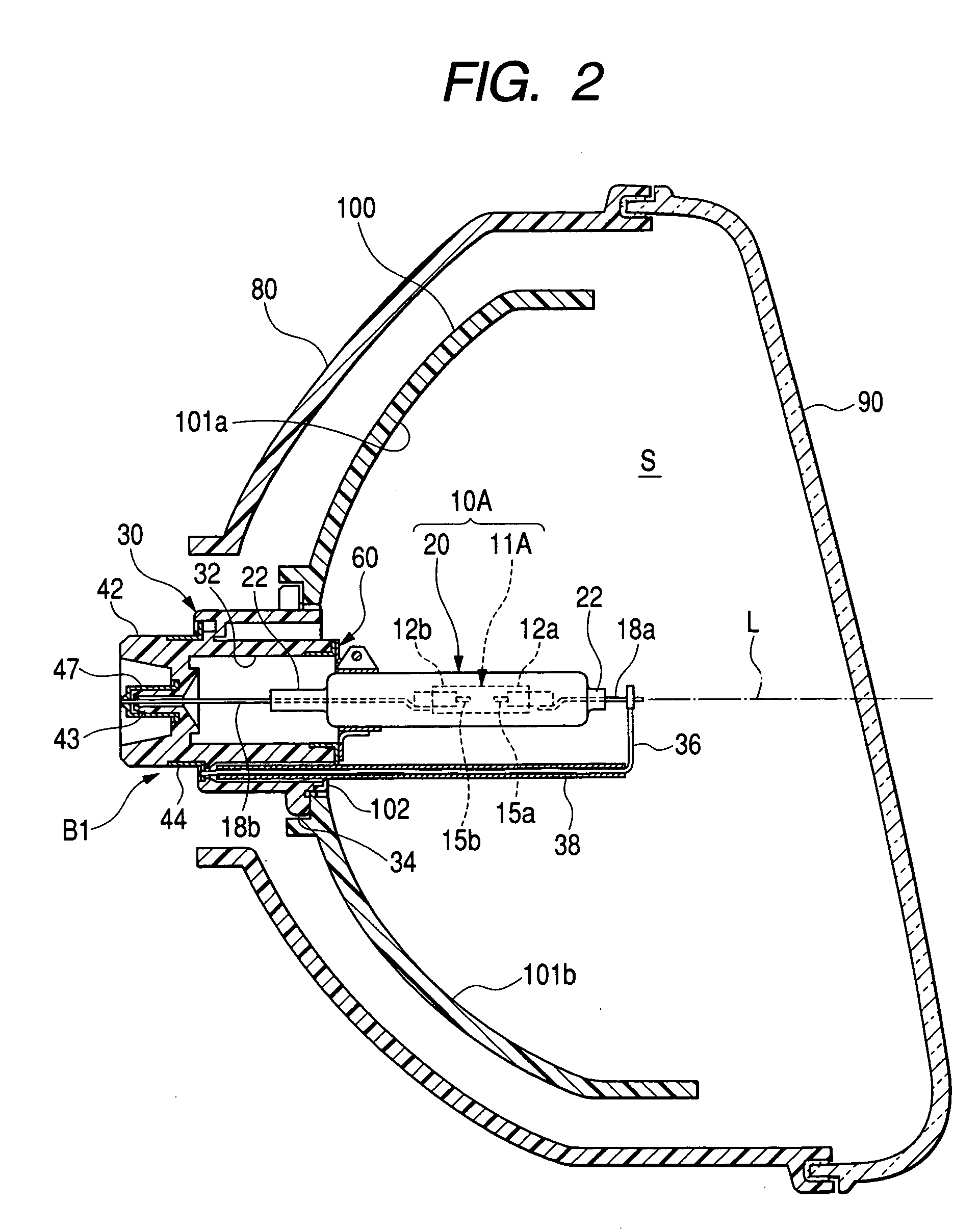
[0010] The invention is accomplished in view of the problems of the related discharge bulb. Accordingly, an object of the invention is to provide an automotive discharge bulb enabled to have good rising characteristic of luminous flux and luminous efficiency and to alleviate the required thermal shock resistance of the ceramic tube, and also to provide an automotive headlamp having this discharge bulb.
[0012] The ceramic tube constituting the light emitting tube is required to be compact. Thus, the capacity of an enclosed space of the light emitting tube (that is, the ceramic tube) is small. Immediately after discharging is commenced, the temperature of the enclosed space becomes high. Consequently, the ceramic tube has a good rising characteristic of luminous flux. Also, the surface area of the ceramic tube is small. Thus, a load (W / cm2)imposed on the wall surface increases. Consequently, the ceramic tube has good luminous efficiency.
[0013] Although an arc generated by discharge between the electrodes has an upwardly convex shape, the tube wall is not brought into large contact with the high-temperature arc, because the transversal section of the ceramic tube is longitudinally elongated. Consequently, a thermal shock resistance characteristic required of the ceramic tube is alleviated.
[0014] Because the tube wall of the ceramic tube is not put into large contact with the high-temperature arc, the amount of heat radiated from the tube wall is reduced. Thus, the enclosed space rapidly reaches a high temperature. Consequently, the rising characteristic of luminous flux is further improved.
[0017] When the inside diameter in the longitudinal direction of the transversal section of the ceramic tube exceeds about 3 mm, the surface area of the ceramic tube increases. Thus, the load (W / cm2) imposed on the tube wall is reduced, and the luminous efficiency of the ceramic tube is correspondingly decreased. Also, an image of a light source is enlarged, so that the light distribution characteristic thereof is degraded. Therefore, preferably, the inside diameter in the longitudinal direction of the transversal section of the ceramic tube is equal to or less than 3 mm.
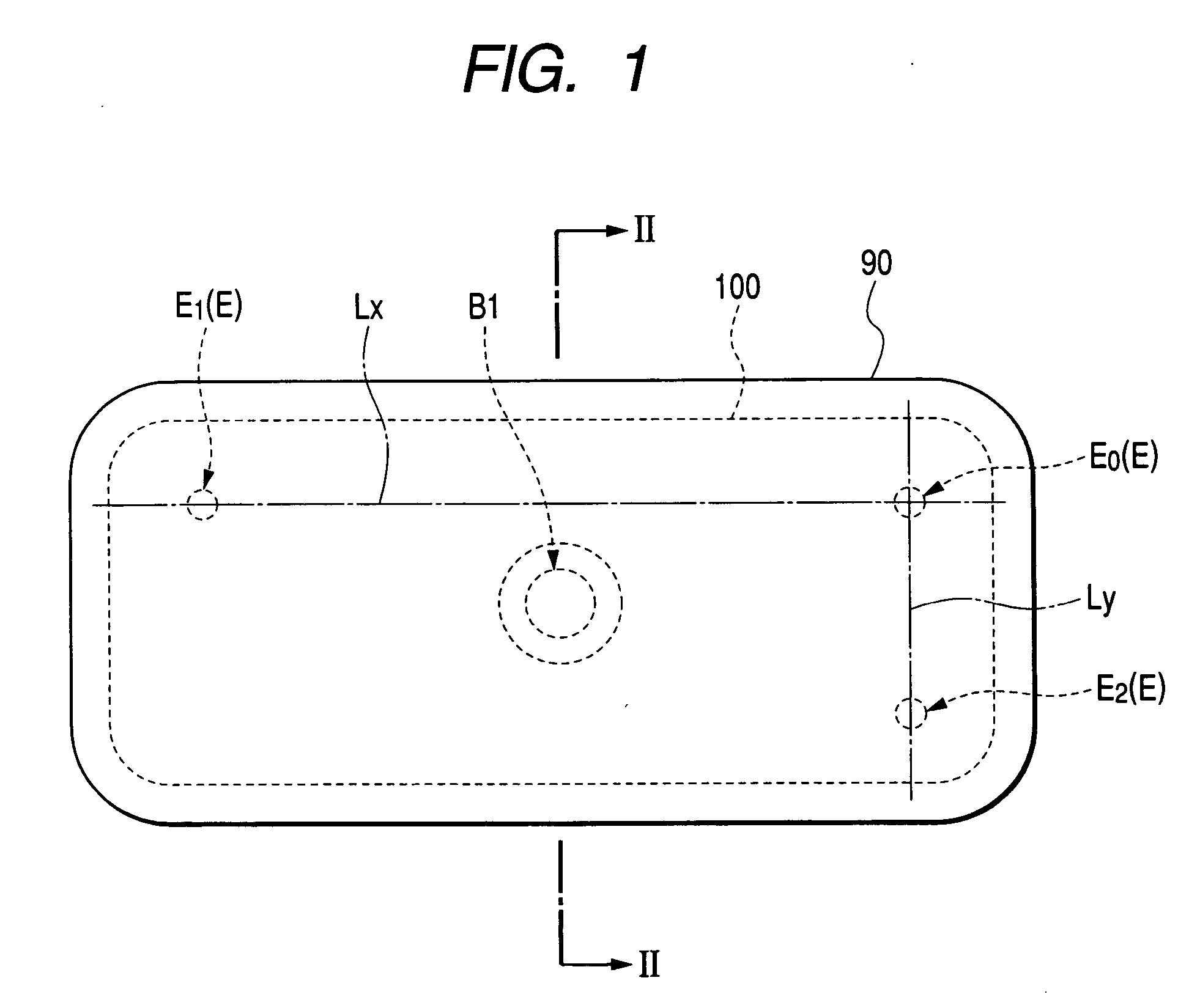
[0024] The recent automotive headlamp has a tendency to use a latitudinally elongated reflector (that is, a reflector whose dimension in a lateral direction is larger than a dimension in an upward-downward direction thereof). Thus, light emitted upwardly and downwardly from the light emitting tube is wastefully consumed. However, the exemplary, non-limiting automotive headlamp of the invention is configured so that the dimension in the widthwise direction of the ceramic tube constituting the light emitting tube is shorter than the dimension in the longitudinal direction thereof. Consequently, the proportion of the wastefully consumed light can be reduced.

Problems solved by technology

However, the related art discharge bulb has encountered problems.
For example, but not by way of limitation, metal halide filled in the light emitting tube promotes corrosion of the light emitting tube (or glass tube).
Further, blackening and devitrification phenomena occur.
Thus, no appropriate light distribution is obtained, and the life of the discharge bulb is not very long.
Consequently, very limited ceramic materials are available as the material of the ceramic tube of the light emitting tube.
The related discharge bulb has another problem that when the central part of the high-temperature arc is put into large contact with the tube wall, an amount of heat radiated from the tube wall increases, and this increase in the amount of radiated heat delays the rise in luminous flux.

Method used


Image

  • Automotive discharge bulb and automotive headlamp
  • Automotive discharge bulb and automotive headlamp
  • Automotive discharge bulb and automotive headlamp

Examples


fourth embodiment

[0077]FIGS. 11 and 12 illustrate a light emitting tube, which is a primary part of a discharge bulb that is the invention. FIG. 11 is a vertically longitudinally sectional view illustrating this light emitting tube. FIG. 12 is a vertically transversally sectional view illustrating this light emitting tube, which is taken along line XII-XII shown in FIG. 11.

[0078] In any of the first to third embodiments, the electrodes 15a, 15b are respectively and integrally joined to the ceramic tubes 12, 12A through the molybdenum pipes 14, 14A. However, in an arc tube 10D (a light emitting tube 11D) of a discharge bulb B4 of this fourth embodiment, the electrodes 15a, 15b are passed through a circular hole 13a of a ceramic blocking member 13B, which has an elliptic transversal section (the outer periphery thereof is elliptic and the inner periphery thereof is perfectly circular) and is integrally sintered to each of both end portions of the ceramic tube 12 having an elliptic transversal section....

fifth embodiment

[0080] FIGS. 13 to 16 illustrate a light emitting tube, which is a primary part of a discharge bulb that is the invention. FIG. 13 is a vertically longitudinally sectional view illustrating this light emitting tube. FIG. 14 is a vertically transversally sectional view illustrating this light emitting tube, which is taken along line XIV-XIV shown in FIG. 13. FIG. 15 is a perspective view illustrating this light emitting tube. FIG. 16 is an explanatory view illustrating the shape of this light emitting tube.

[0081] In an arc tube 10E (a light emitting tube 11E) of a discharge bulb B5 of this fifth embodiment, a ceramic tube 12B is of the type in which the blocking portions and the ceramic tube 12B are integrally formed, and similarly to the third embodiment (see FIGS. 9 and 10). However, the fifth embodiment features a light emitting portion region 12c, which has an elliptic transversal section and is adapted to emit light in response to discharge between the electrodes 15a, 15b, and b...


PUM

PropertyMeasurementUnit
lengthaaaaaaaaaa
lengthaaaaaaaaaa
diameteraaaaaaaaaa

Abstract

An automotive discharge bulb having a light emitting tube includes a ceramic tube with paired electrodes oppositely placed, and contains a light emitting material and starting rare gas. A transversal section of the ceramic tube is longitudinally elongated. Because the capacity of an enclosed space of the ceramic tube is small, after discharging begins, the enclosed space temperature increases. Consequently, the ceramic tube has a good luminous flux rising characteristic. Because of the small surface area of the ceramic tube, the load imposed on the wall surface increases. Consequently, the ceramic tube has good luminous efficiency. In the ceramic tube having a longitudinally elongated transversal section, an arc generated into an upwardly convex shape and the tube wall do not make contact. Thermal shock resistance required of the ceramic tube is alleviated, durability is enhanced, and the ceramic tube is made of a ceramic material hitherto unusable.

Description

[0001] This application claims foreign priority based on Japanese patent application JP 2003-161016, filed on Jun. 5, 2003, the contents of which is incorporated herein by reference in its entirety. BACKGROUND OF THE INVENTION [0002] 1. Field of the Invention [0003] The present invention relates to an automotive discharge bulb having a light emitting tube that includes a ceramic tube in which electrodes are oppositely placed. The light emitting tube is filled with a light emitting material and a starting rare gas. The present invention further relates to an automotive headlamp having the discharge bulb. [0004] 2. Description of the Related Art [0005] Generally, a discharge bulb having a glass arc tube is used as a light source for an automotive headlamp. However, the related art discharge bulb has encountered problems. For example, but not by way of limitation, metal halide filled in the light emitting tube promotes corrosion of the light emitting tube (or glass tube). Further, blac...

Claims


Application Information

Patent Timeline
Patent Type & Authority Applications(United States)
IPC IPC(8): F21S8/12F21V13/00F21W101/10F21S8/10F21Y101/00H01J7/24H01J17/20H01J61/26H01J61/30H01J61/33H01J61/34H01J61/82H01K1/58
CPCH01J61/26H01J61/30H01J61/827H01J61/34H01J61/33
Inventor TSUDA, TOSHIAKIKINOSHITA, MASAO
Owner KOITO MFG CO LTD
Learn More