Headlamp for vehicle

a headlamp and vehicle technology, applied in the direction of fixed installation, lighting and heating equipment, lighting support devices, etc., can solve the problems of improper light source of the headlamp for the vehicle, reducing the luminous flux of the light source, etc., and achieves the effect of suppressing the rise in the temperature of the semiconductor light emitting unit and efficiently cooling the metal support member

Active Publication Date: 2006-10-03
KOITO MFG CO LTD
View PDF14 Cites 82 Cited by
  • Summary
  • Abstract
  • Description
  • Claims
  • Application Information

AI Technical Summary

Benefits of technology

[0025]More specifically, the lowest temperature is obtained in the lamp housing in the vicinal position of the lower end of the translucent cover. If the heat pipe can be extended to the vicinal position of the lower end of the translucent cover, therefore, the metallic support member can be cooled efficiently. In addition, warm air is brought up by a heat exchange in the tip portion of the heat pipe at this time so that the translucent cover can be warmed up at an internal surface side thereof. Also in the case in which a blur is generated on the internal sur

Problems solved by technology

For this reason, there is a problem in that the luminous flux of a light source is decreased or a luminescent color is changed

Method used


Image

  • Headlamp for vehicle
  • Headlamp for vehicle
  • Headlamp for vehicle

Examples


Embodiment Construction

[0036]An embodiment of the invention will be described below with reference to the drawings.

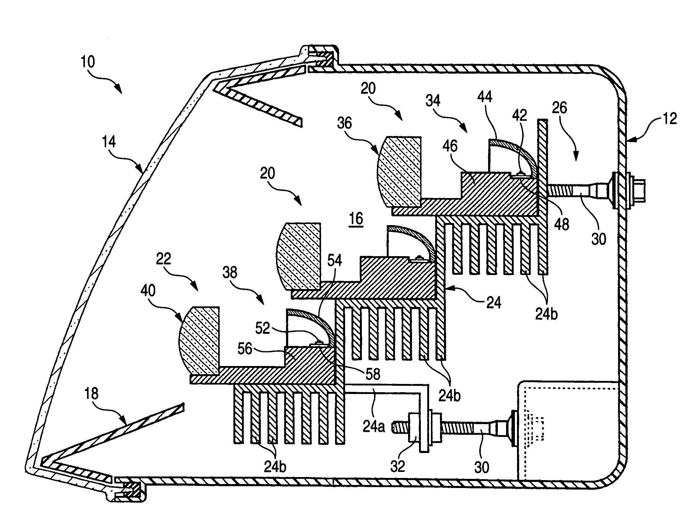
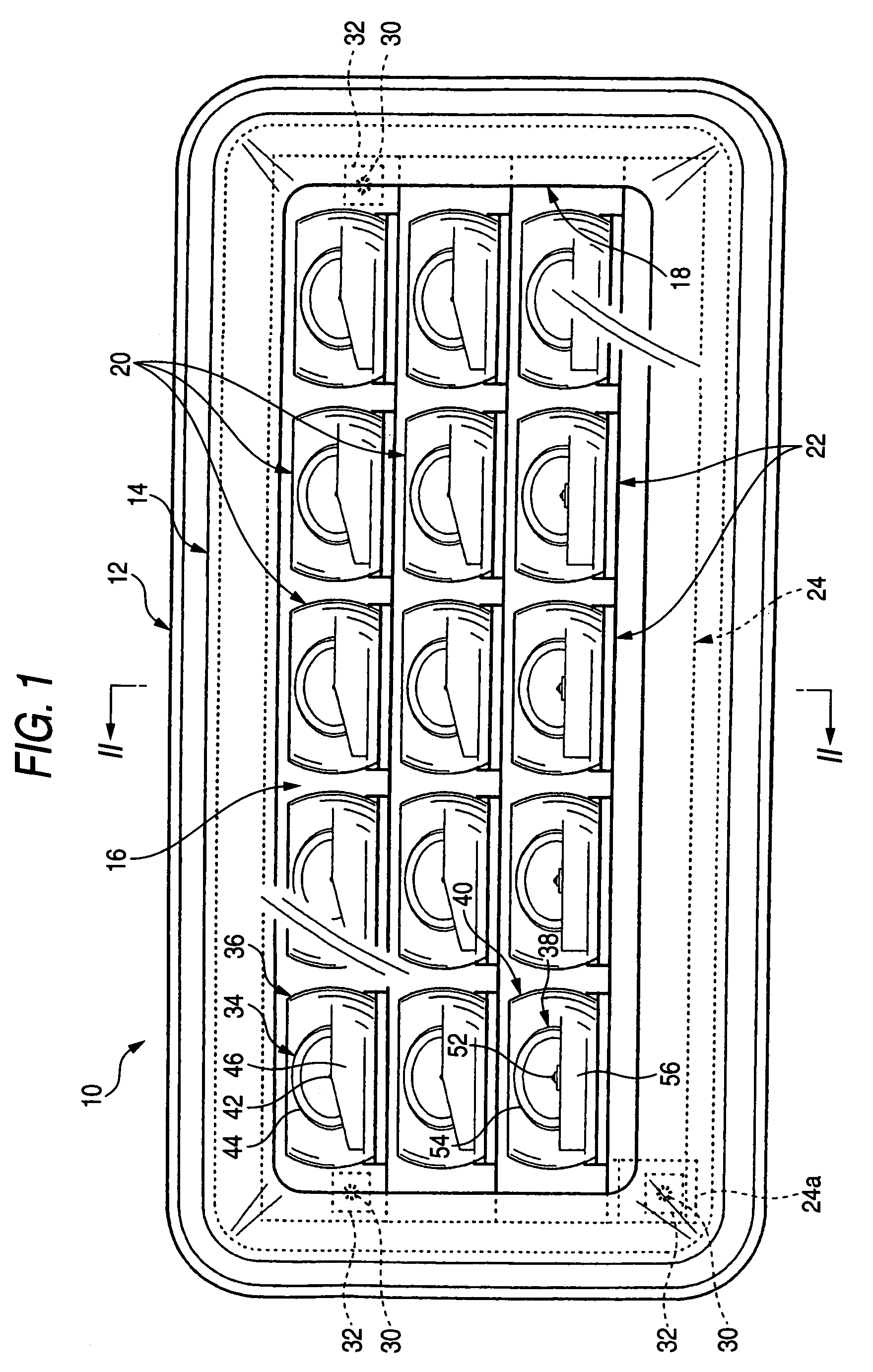
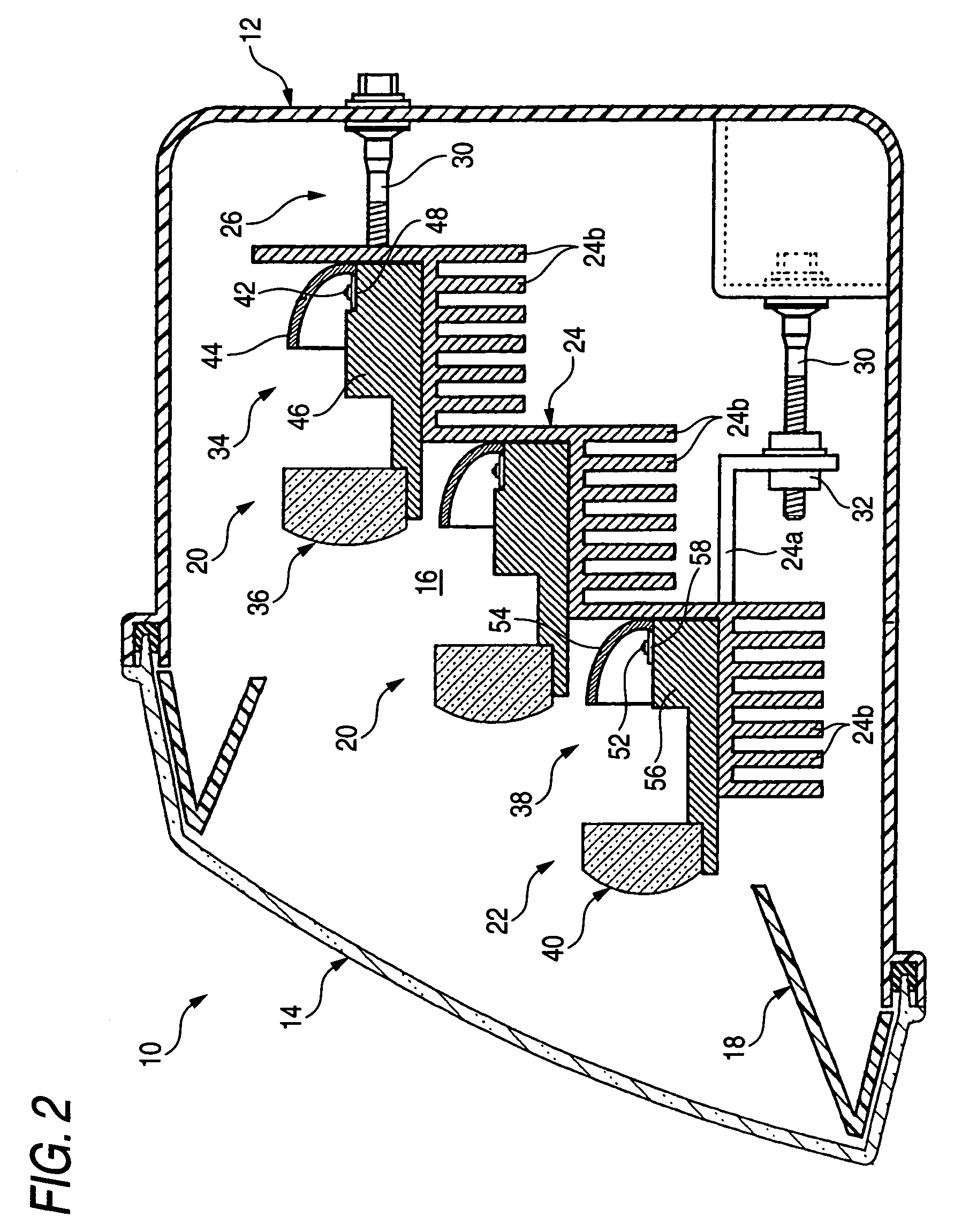
[0037]FIG. 1 is a front view showing a headlamp 10 for a vehicle according to an embodiment of the invention, and FIG. 2 is a sectional view taken along a II—II line in FIG. 1.

[0038]In the headlamp 10 for a vehicle, 15 lighting units 20 and 22 are accommodated in a lamp housing 16 formed by a lamp body 12 and a translucent cover 14 attached to an opening portion on a front end thereof, every five lighting units 20 and 22 being arranged in three vertical stages, and an extension reflector 18 is provided on a front end in the lamp housing 16 in order to substantially surround these lighting units 20 and 22.

[0039]Ten lighting units 20 positioned in upper and middle stages serve to form a light distribution pattern for a low beam, and five lighting units 22 positioned in a lower stage are additionally turned on when a light distribution pattern for a high beam is to be formed.

[0040]These 15 light...


PUM


Abstract

A plurality of lighting units using light emitting diodes as light sources is accommodated in a lamp housing in such a state as to be supported on a common metallic support member provided tiltably. When a part or all of the lighting units are turned on, the light emitting diodes generate heat with a light emission. These light emitting diodes are supported on the common metallic support member. Also in the case in which any of the lighting units is turned on, therefore, the heat generated by the light emitting diodes is moved to the metallic support member having a large heat capacity through boards and light source support blocks by a heat conducting function. Consequently, a rise in the temperatures of the light emitting diodes can be suppressed.

Description

[0001]The present invention claims priority based on Japanese patent application no. 2003-103674, filed Apr. 8, 2003, the contents of which is incorporated herein by reference.BACKGROUND OF THE INVENTION[0002]1. Technical Field[0003]The present invention relates to a headlamp for a vehicle, which forms various light distribution patterns by lighting units using a semiconductor light emitting unit as a light source.[0004]2. Related Art[0005]Conventionally, a marker lamp for a vehicle such as a tail lamp has often used a light emitting diode as a light source thereof. For example, related art Japanese publication JP-A-2001-332104 describes a marker lamp for a vehicle in which a plurality of lighting units using a light emitting diode as a light source is arranged.[0006]In recent years, the luminance of a light emitting diode has been enhanced and there is a growing tendency to employ the light emitting diode as a light source of a headlamp for a vehicle.[0007]When the luminance of the...

Claims


Application Information

Patent Timeline
IPC IPC(8): F21V14/00B60Q1/06F21S8/10F21V14/02F21V19/00F21V29/00F21V31/03F21W101/10F21Y101/02
CPCF21S48/1159F21S48/1163F21S48/25F21S48/328F21V29/767F21V29/004F21V29/763F21S48/335F21Y2101/02F21V29/006F21Y2115/10F21S41/148F21S41/151F21S41/155F21S43/50F21S45/43F21S45/48F21S45/60F21S45/47F21W2102/00F21V29/74
Inventor YAGI, SEIICHIROOISHI, KAZUTAMIINOUE, TAKASHISASAKI, MASARU
Owner KOITO MFG CO LTD
Why Eureka
Try Eureka