Air drying device for a pneumatic system

Inactive Publication Date: 2000-06-20
AB VOLVO
View PDF17 Cites 39 Cited by
  • Summary
  • Abstract
  • Description
  • Claims
  • Application Information

AI Technical Summary

Problems solved by technology

These methods, however, exhibit some disadvantages.
An example of such a disadvantage is that equipment for the handling of alcohol injections must be added to the compressed air system.
A second disadvantage is that such a system consumes and emits alcohol to the ambient air.
However, the ceramic material may only hold a certain quantity of water; thereafter the holding capacity is saturated and the air is not dried any more.
This system exhibits an disadvantage in those cases when a lot of compressed air is consumed incidentally, for instan

Method used


Image

  • Air drying device for a pneumatic system
  • Air drying device for a pneumatic system
  • Air drying device for a pneumatic system

Examples


Embodiment Construction

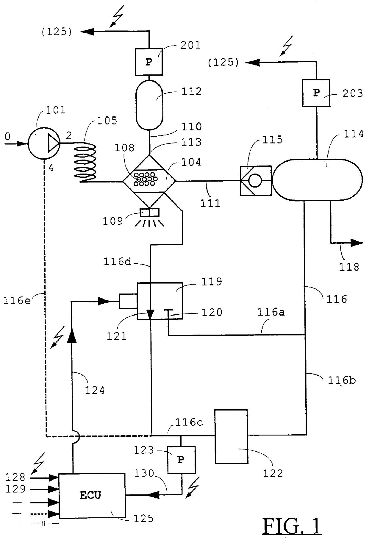
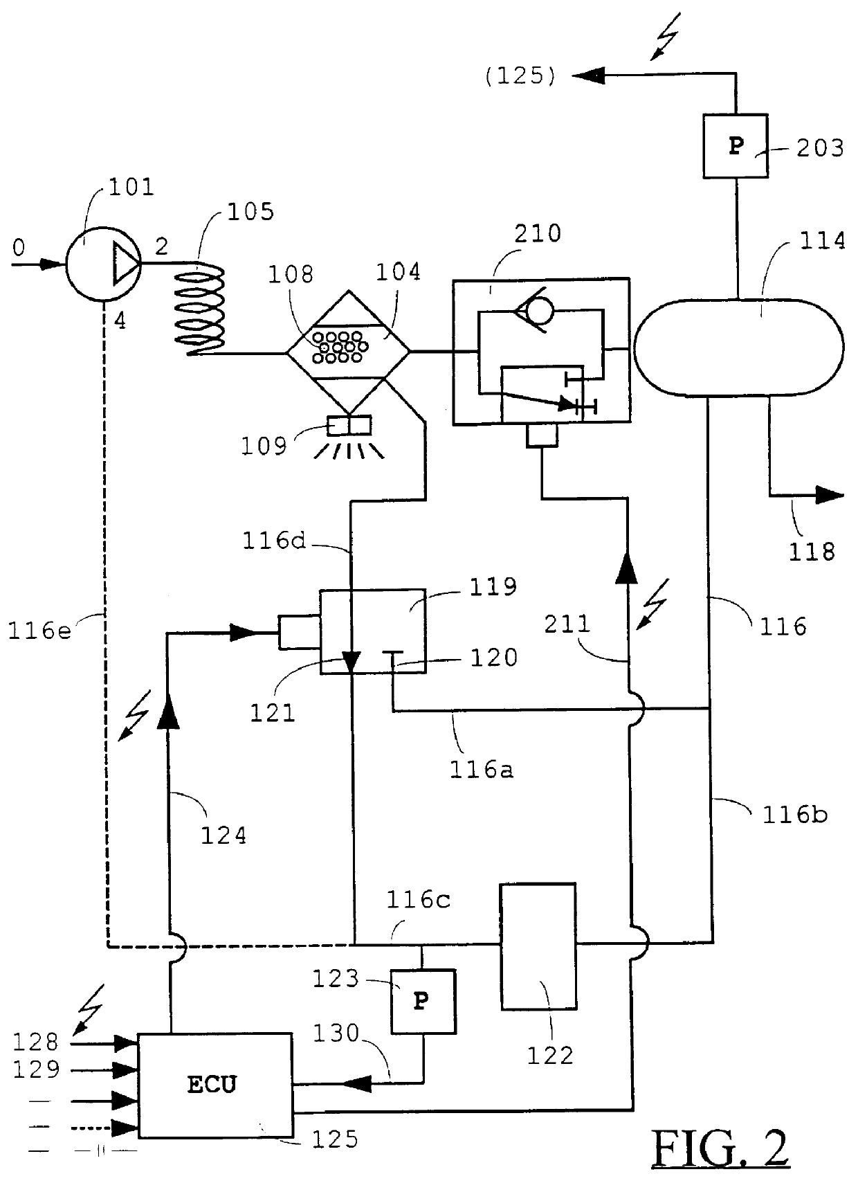
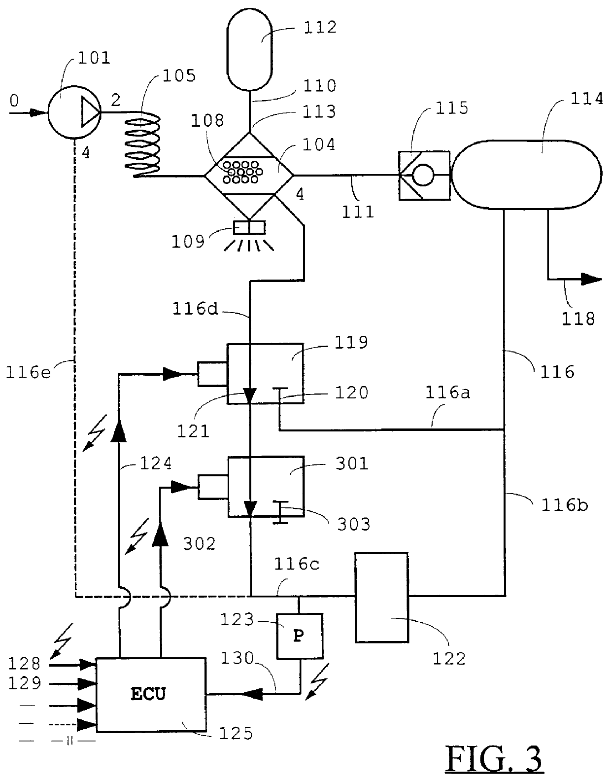
A compressor 101 is connected to a compressed air system. The compressor has an inlet 0 where air is sucked into the system, and an outlet 2 where compressed air flows towards the dehumidifier 104. A cooling coil 105 is connected between the compressor and the dehumidifier. The purpose of the cooling coil is to cool the air, which implies that a portion of the water vapour, being part of the air, will be condensed. The condensed water is collected on the bottom of the dehumidifier. A drying agent, consisting of a multitude of porous zeolite balls 108, is included in the dehumidifier. A valve 109 is connected in the lower portion of the dehumidifier.

Two conduits 110 and 111 are connected to the dehumidifier. The conduit 110 leads to a drying air container 112. The conduit 110 is provided with a throttle 113. The throttle may be designed as a small hole between the drying air container and the dehumidifier. The task of the throttle is to ensure that the drying air container is evacuat...


PUM

PropertyMeasurementUnit
Temperatureaaaaaaaaaa
Pressureaaaaaaaaaa
Speedaaaaaaaaaa

Abstract

PCT No. PCT/SE96/01162 Sec. 371 Date Jun. 10, 1998 Sec. 102(e) Date Jun. 10, 1998 PCT Filed Sep. 20, 1996 PCT Pub. No. WO97/11274 PCT Pub. Date Mar. 27, 1997Device and method for the regeneration of a drying agent in compressed air system. The wetting degree of the drying agent is estimated and recorded by a control unit. The control unit ensures that the drying agent is dehumidified as soon as the wetting degree has reached a certain wetting degree. This certain wetting degree may be set to different levels for different operational condition.

Description

The present invention relates to a dehumidifying device for a single-tower dryer in a compressed air system. The device comprises a control unit, a compressor, a container which is connected to the compressor via a first connection and filled with drying agent, a first and a second pressure tank which are connected to the container via a second and a third connection, of which the first pressure tank serves as an air tank for prospectively connected consumers of compressed air, and the second pressure tank serves as an air tank for dried air intended to be used for dehumidification of the drying agent, a first valve which is connected to the container and which may adopt a first position when a connection between the interior of the container and the ambient atmosphere is open, and a second position when the connection between the interior of the container and the ambient atmosphere is closed, and also a second valve, controlled by the control unit.The present invention also relates...

Claims


Application Information

Patent Timeline
IPC IPC(8): B01D53/26F04B39/16F04B41/00
CPCB01D53/261F04B39/16Y10S55/17F04B2207/02
Inventor SABELSTROM, MATS
Owner AB VOLVO
Why Eureka
Try Eureka