Process and arrangement for the evaluation of laser doppler signals

a laser and doppler technology, applied in the direction of reradiation, devices using optical means, analysing solids using sonic/ultrasonic/infrasonic waves, etc., can solve the problem that the vco cannot compensate for the large changes in the doppler frequency sufficiently, cannot be used for small doppler frequency, and cannot solve the problem of large phase variation caused by small phase variations, etc., to achieve the effect of low velocity

Inactive Publication Date: 2000-06-20
JENOPTIK
View PDF4 Cites 20 Cited by
  • Summary
  • Abstract
  • Description
  • Claims
  • Application Information

AI Technical Summary

Benefits of technology

The technical effect of this patented technology allows us to evaluate laser-Doppler (LD) signal patterns that have certain benefits but still allow reliable measurement at very small velocity levels or when there are no particles flowing continuously over time without losing their accuracy.

Problems solved by technology

The technical problem addressed in this patent text is the need for accurate and stable measurement of velocities and quantities derived from laser Doppler devices, despite the fact that the frequency range to be evaluated must always contain the entire width of the possible Doppler frequency. The signal-to-noise ratio is inversely proportional to the filter bandwidth, so it is necessary to keep the filter bandwidth as small as possible. The patent text describes various methods for frequency tracking demodulation, including the use of frequency discriminators and phase discriminators, as well as homodyne and heterodyne tracking methods. However, each method has its limitations, such as the narrow linear range of frequency characteristics of frequency discriminators and the susceptibility to small phase variations in phase discriminators. The patent text also discusses the issue of signal dropouts, which can significantly impact the accuracy and stability of the Doppler frequency measurement.

Method used


Image

  • Process and arrangement for the evaluation of laser doppler signals
  • Process and arrangement for the evaluation of laser doppler signals
  • Process and arrangement for the evaluation of laser doppler signals

Examples


example 2

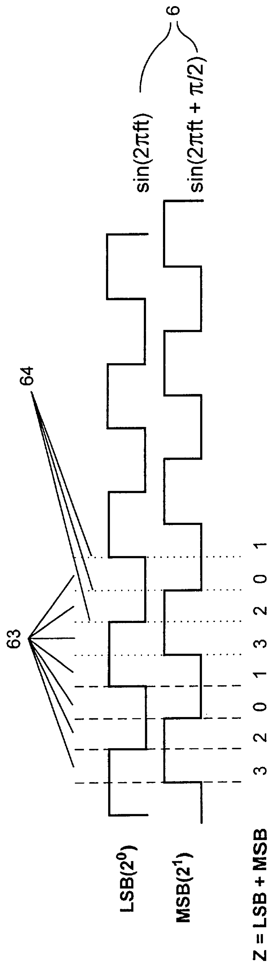
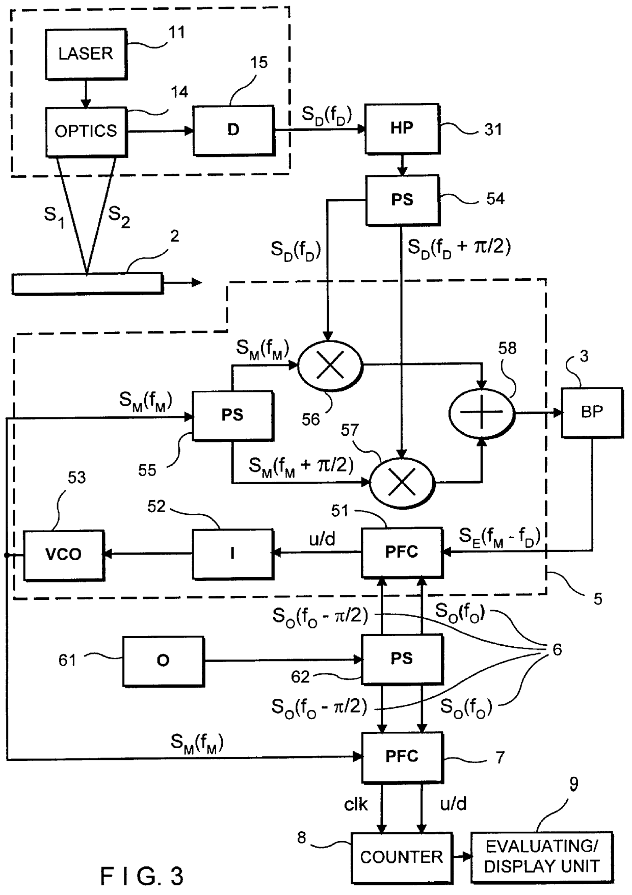
A device having as its object a homodyne LDA is described with reference to FIG. 3. In this case, additional changes according to the invention are needed in known LDA's in order to be able to apply the orthogonal frequency system 6 for phase detection based on the fundamental principle of frequency tracking demodulation.

As is shown in FIG. 3, the LDA 1 has only one laser 11 and optics 14 and accordingly no frequency offset. As in Example 1, the sending beams S.sub.1 and S.sub.2 formed by beam splitting are directed onto the measurement object 2 in crossbeam geometry, so that the scattered light is received and transformed in conventional manner by the detector 15. The detector 15 is preferably followed by a high-pass filter 31 in order to eliminate the dc light component.

In this case, instead of the electronic mixer 4 used in Example 1, a larger network is required before a mixed Doppler signal can be filtered at the bandpass filter 3. The control loop 5 is accordingly configured i...

example 3

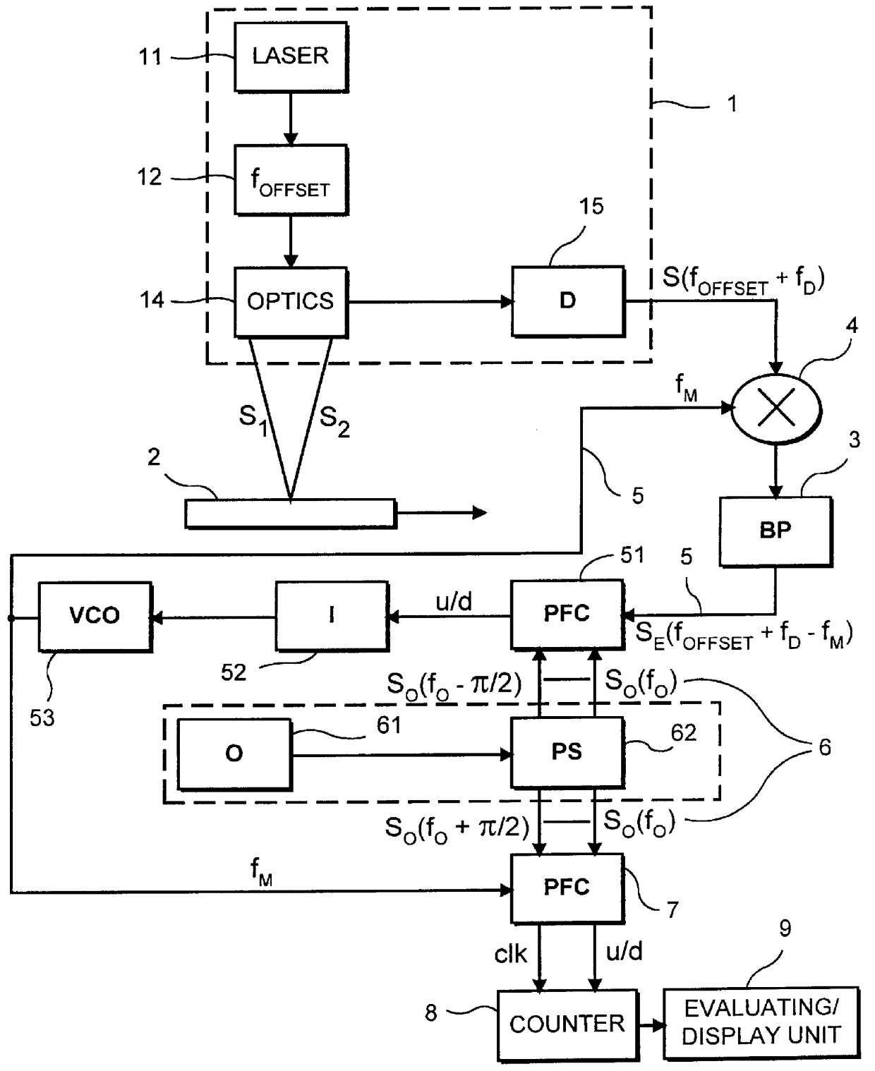
The device shown in FIG. 4 is a heterodyne LDA 1 with frequency offset, wherein the laser light from laser 11 passes through a frequency offset unit 12 after beam splitting before being directed by means of optics 14 as sending beams S.sub.1 and S.sub.2 in the preferable crossbeam arrangement onto a measurement location and guided as scattered light from the measurement object 2 to the detector 15.

The transformed, preamplified detector signal S.sub.D (f.sub.offset +f.sub.D) is filtered in narrowband in the bandpass filter 3 and changed into rectangular signals. The control loop 5 processes the output signal of the bandpass filter 3 initially, as in Example 1, via a PFC 51, integrator 52 and VCO 53. However, the output signal of the VCO 53 is then used to directly control the frequency offset unit 12, wherein the VCO 53 delivers the offset frequency f.sub.offset. A baseband shift is accordingly carried out depending on the change in the Doppler frequency f.sub.D, wherein the particul...

example 4

FIG. 5 shows a heterodyne LDA 1 with phase modulation which is based on the double modulation principle known from DE 195 37 647 C1.

The LDA 1 comprises a laser 11 whose light is split into partial beams, passes through an optical phase modulator 13, wherein at least one partial beam is modulated with two different modulation frequencies which are coupled so as to be fixed with respect to phase and frequency, one of which is a whole-number multiple of the other modulation frequency, and subsequently, as is conventional in crossbeam arrangements, is directed onto the measurement object 2 via optics 14 as two sending beams S.sub.1 and S.sub.2. The scattered light of the sending beams S.sub.1 and S.sub.2 is received in a known manner by the detector 15, whose output signal is supplied to the bandpass filter 3. As in the preceding examples, following the bandpass filter 3, the control loop 5 contains a PFC 51, an integrator 52 and a VCO 53, wherein the PFC 51 compares the signal coming f...


PUM


Abstract

Processes and arrangements for the evaluation of laser Doppler signals, especially in laser Doppler anemometers (LDA) or vibrometers, are disclosed. The object of these processes and arrangements is to find a simple possibility for evaluating laser Doppler signals which retains the advantages of conventional frequency tracking demodulation and permits dependable actual measurements of velocities and derived movement values also for extremely low velocities and discontinuous particle flows. This object is achieved with the use of a laser Doppler anemometer (LDA) with bandpass filtration and frequency tracking demodulation, by generating at least one orthogonal frequency system which, as a sequence of four state intervals in an invertible one-to-one correlation, is formed of two additively superimposed rectangular functions with a phase displacement of pi /2, a detector signal containing the Doppler frequency (fD) is compared after bandpass filtering with respect to its phase with the state intervals of the orthogonal frequency system, wherein a change in the phase position relative to the orthogonal frequency system triggers a compensation of the change in Doppler frequency generating a regulated mixing frequency (fM) which is coupled into the LDA, and the regulated mixing frequency (fM), as an equivalent of the Doppler frequency (fD), is likewise compared with an orthogonal frequency system and, as a result of the one-to-one sequence of state intervals, is evaluated such that the direction is designated.

Description


Claims


Application Information

Patent Timeline
Owner JENOPTIK
Why Eureka
Try Eureka