Connection device for multiple-core optical fibres based on optical elements in free space

a technology of free space and connection device, applied in the field of multi-core optical fibre, can solve problems such as inability to adapt to connections of any geometry

Inactive Publication Date: 2000-06-20
FRANCE TELECOM SA
View PDF6 Cites 27 Cited by
  • Summary
  • Abstract
  • Description
  • Claims
  • Application Information

AI Technical Summary

Problems solved by technology

They have the disadvantage of not being adaptable...

Method used


Image

  • Connection device for multiple-core optical fibres based on optical elements in free space
  • Connection device for multiple-core optical fibres based on optical elements in free space
  • Connection device for multiple-core optical fibres based on optical elements in free space

Examples


Embodiment Construction

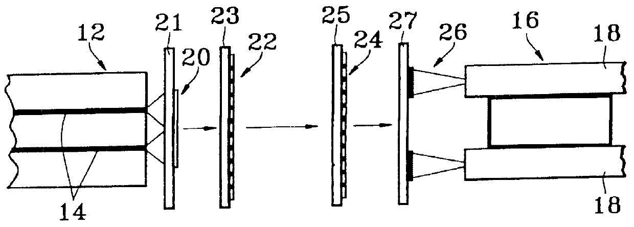
FIG. 3 is a cross section view illustrating a device of the invention.

This device is intended to connect a multiple-core optical fibre 12 comprising several cores 14, of which two are shown in FIG. 3, to an end optical component 16 comprising several elementary optical components 18, of which two are shown in FIG. 3.

With this device it is possible to optically connect cores 14 of fibre 12 respectively to elementary components 18, each core being connected optically to an elementary component.

In accordance with the present invention, the device of FIG. 3 uses connections in free space.

In this respect reference may be made to document (5).

These connections are made by means of a multiplicity of groups of diffractive and / or refractive micro-optical elements 20, 22, 24 and 26.

At least one of these groups is made up of diffractive micro-optical elements and is given reference 22 in FIG. 3.

The choice of connections in free space arises from the two-dimensional configuration of the end par...


PUM


Abstract

Connection device for multiple-core optical fibers based on optical elements in free space. This device comprises a first optical means (36) which is refractive or diffractive, and at least one second means (38, 40) which is diffractive. The first means causes the light beams exiting cores (30) of fiber (28) to diverge as far as an area in which these beams are separated in space and have cross sections whose size is compatible with the spatial bandpass of the second means. The latter is positioned in this area and directs the beams, independently from one another, towards corresponding optical components (34). Application to optic telecommunications.

Description

The present invention relates to a connection device for multiple-core optical fibres.It particularly applies to optic telecommunications.STATE OF PRIOR ARTA multiple-core optical fibre may have the outer diameter of a standard monomode optical fibre with a single core (125 .mu.m), but it contains multiple cores, typically from 4 to 10 cores.Preferably the diameter of the cores is substantially equivalent to that of the core of a monomode fibre (8 .mu.m) and these cores are distanced by approximately 40 .mu.m.On the subject of multiple-core optical fibres reference may be made to documents (1) to (4) which, like the other documents quoted herein, are given at the end of the present disclosure.An example of a multiple-core optical fibre 2 is illustrated in a cross-section diagram in FIG. 1 of the appended drawings.In this example, multiple-core fibre 2, whose outer diameter D is 125 .mu.m, contains four cores carrying reference 4, which are positioned at the top corners of a square w...

Claims


Application Information

Patent Timeline
IPC IPC(8): G02B6/28G02B6/42
CPCG02B6/2848G02B6/02042G02B6/4249
Inventor DE LA TOCNAY, JEAN-LOUIS DE BOUGRENETCHEVALLIER, RAYMONDHEGGARTY, KEVINDEFOSSE, YVES
Owner FRANCE TELECOM SA
Why Eureka
Try Eureka