Automatic tracking lighting equipment, lighting controller and tracking apparatus

a technology of lighting controller and lighting equipment, applied in the direction of electric programme control, program control, instruments, etc., can solve the problems of labor and burden on the operator, and inability to work normally

Inactive Publication Date: 2000-06-27
MATSUSHITA ELECTRIC WORKS LTD
View PDF11 Cites 229 Cited by
  • Summary
  • Abstract
  • Description
  • Claims
  • Application Information

AI Technical Summary

Problems solved by technology

In the automatic tracking lighting equipment having the above construction, in order to correctly specify the position of the transmitter, it has been required to provide a number of receivers on the ceiling surface of the lighting space and clarify a positional relation between the receivers in the lighting space, leading to the problem that an inferior workability results.
This arrangement has the problem that the operator is required to have a skill to a certain extent and labor and burden are imposed on the operator.
This arrangement has the problem that labor and burden are imposed on the operator.
Therefore, the mounting positions must be measured, and this causes the problem that a considerable labor is required for the initial setting.
Therefore, when the shape of the object to be tracked changes (e.g., when the object to be tracked is a human being), the cumulative value of the absolute values of the difference in the correct position disadvantageously increases, and this has sometimes led to a failure in tracking the object to be tracked.
Furthermore, there has been the problem that a degraded tracking accuracy has resulted in an environment where a number of objects having a shape similar to that of the object to be tracked exist.
However, the color information changes when the distance and angle between the object to be tracked and the light changes in the course of tracking, and therefore, the stored color information cannot be extracted, possibly leading to a difficulty in tracking.
However, there has been the problem that the marker is sometimes made invisible by the object to be tracked itself or another object, and a number of markers (infrared light transmitters) must be attached to the object to be tracked in order to prevent the occurrence of it.
Furthermore, depending on the environment of use, it is sometimes the case where a light source having an infrared component such as distance measuring equipment or a halogen lamp of a camera exists other than the infrared light transmitter, when the infrared light from other than the infrared light transmitter is disadvantageously tracked, causing a failure in tracking the object to be tracked.
Also, when a reflection marker such as reflection tape or the like is employed, in case there exist a plurality of high luminance points in the lighting rigion by existence of another reflective object, the possibility of wrong recognition of the object to be tracked become higher, by using of the method which specifies the position of the object only by the binarizing data of luminance, and it causes lack of utility.

Method used


Image

  • Automatic tracking lighting equipment, lighting controller and tracking apparatus
  • Automatic tracking lighting equipment, lighting controller and tracking apparatus
  • Automatic tracking lighting equipment, lighting controller and tracking apparatus

Examples


second embodiment

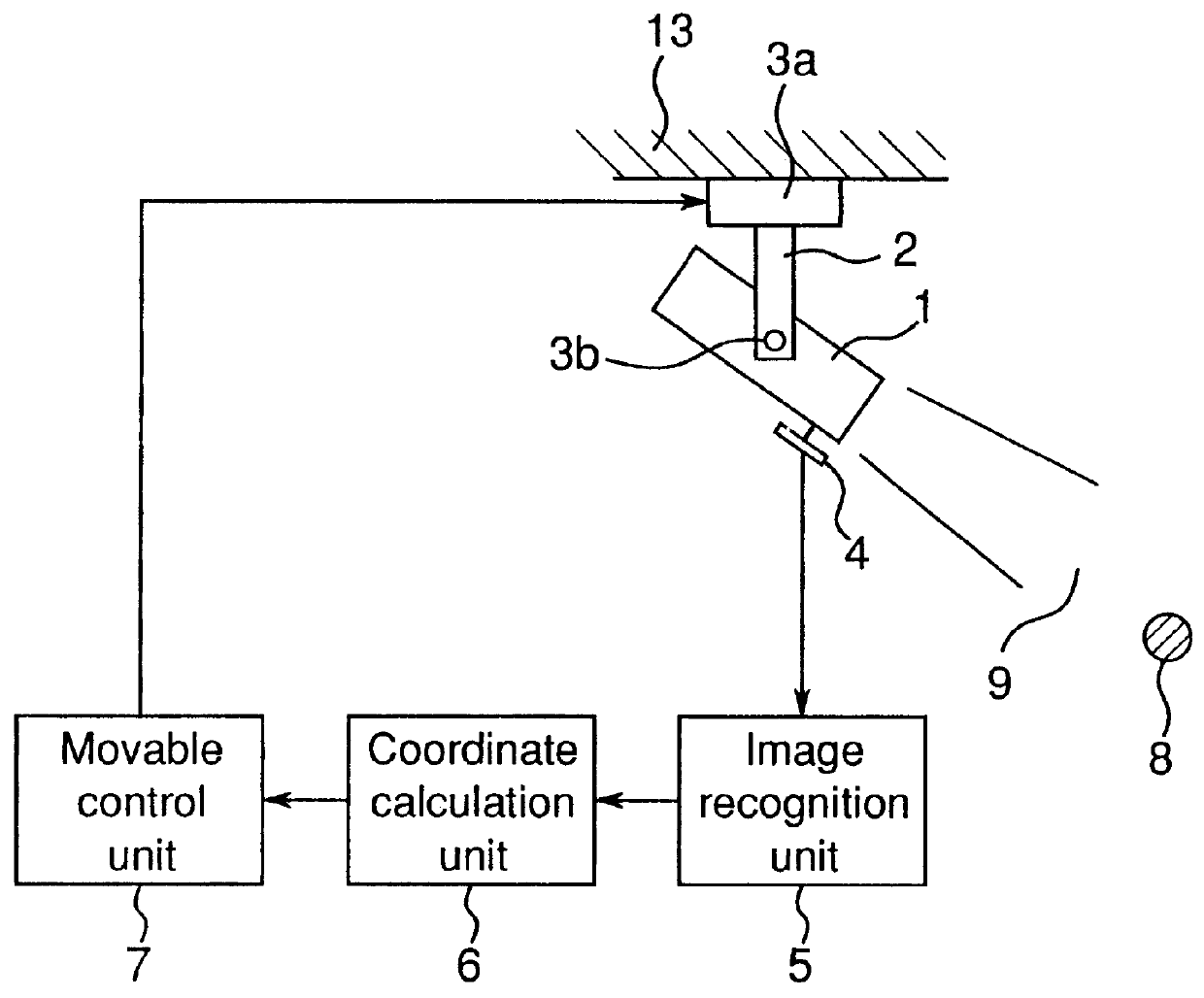
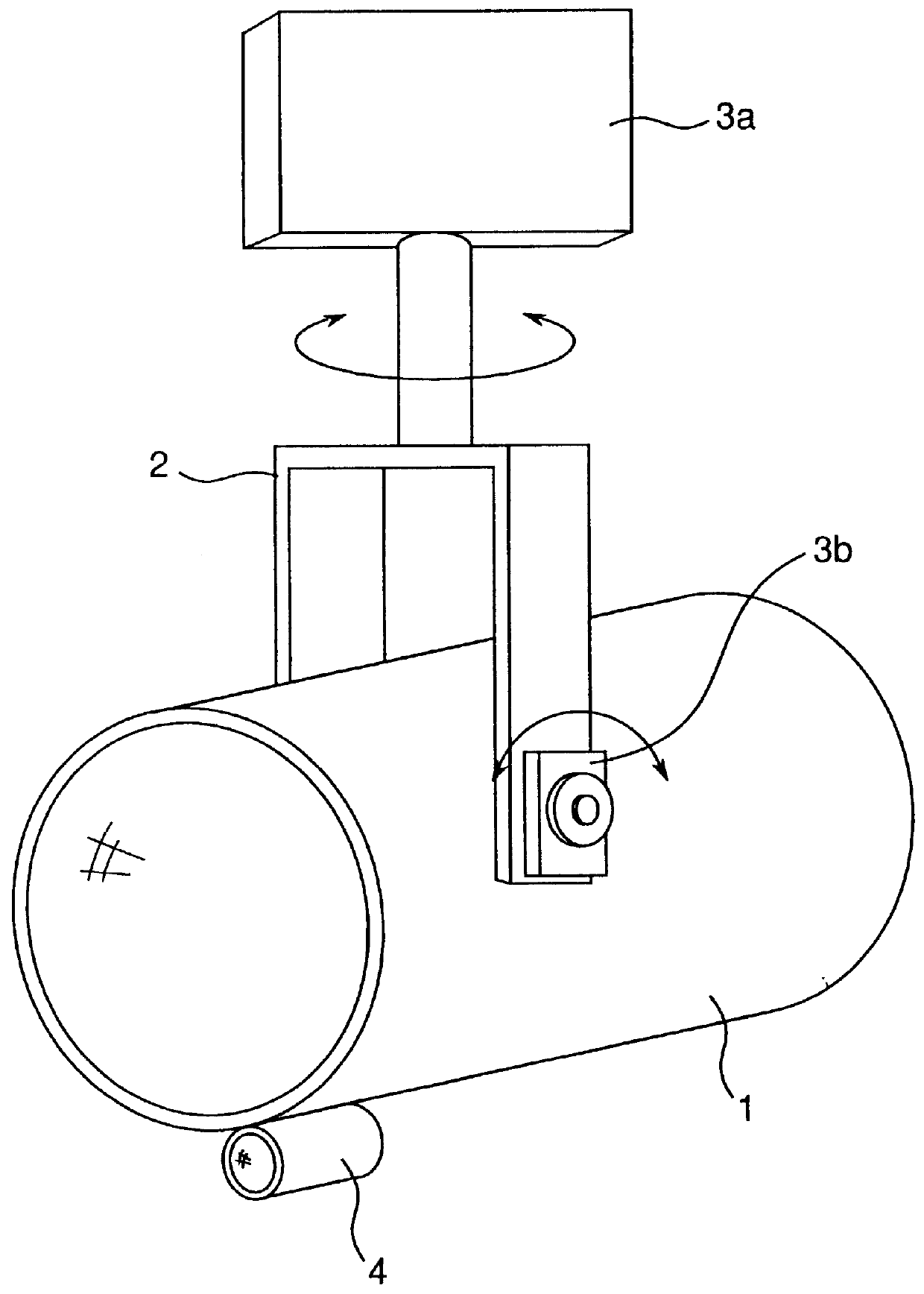
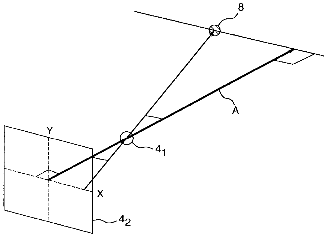
As shown in FIG. 5, the automatic tracking lighting equipment of the present embodiment comprises: a spotlight 1 which serves as a lighting means provided on a ceiling surface 13 of a lighting space 9 for tracking and floodlighting a target to be lighted 8 such as a person in the lighting space 9; a bracket 2 which supports the spotlight 1 pivotally in a horizontal direction and a vertical direction; a horizontal drive means 3a which pivots the spotlight 1 in the horizontal direction; a vertical drive means 3b which pivots the spotlight 1 in the vertical direction; a compact CCD camera 4 which serves as an image pickup means provided on the ceiling surface 13 in a position different from the position of the spotlight 1 and picks up an image in the lighting space 9; an image recognition unit 5 which serves as an image recognizing means for specifying the coordinates of the target to be lighted 8 by processing an image picked up by the CCD camera 4; a coordinate calculation unit 6 whi...

third embodiment

As shown in FIG. 11, the automatic tracking lighting equipment of the present embodiment comprises: a spotlight 1 which serves as a lighting means for tracking and floodlighting a target to be lighted 8 in a lighting space 9; a bracket 2 which supports the spotlight 1 pivotally in a horizontal direction and a vertical direction; a horizontal drive means 3a and a vertical drive means 3b which serve as a first drive means for pivoting the spotlight 1 in the horizontal direction and the vertical direction, respectively; a compact CCD camera 4 which serves as an image pickup means for picking up the image of the target to be lighted 8 in the lighting space 9; a rotating table 10 which serves as a second drive means for making the CCD camera 4 track the movement of the target to be lighted 8; a storage unit 11 which serves as a storage means for storing the image pickup direction of the CCD camera 4; an image recognition unit 5 which serves as an image recognizing means for recognizing t...

fourth embodiment

According to the present embodiment, the automatic tracking lighting equipment of the third embodiment is provided with two CCD cameras which serve as image pickup means for picking up the image of a target to be lighted in a lighting space.

As shown in FIG. 14, this automatic tracking lighting equipment comprises: a spotlight 1 which serves as a lighting means for floodlighting a target to be lighted 8 in a lighting space 9; a bracket 2 which supports the spotlight 1 pivotally in a horizontal direction and a vertical direction; a horizontal drive means 3a and a vertical drive means 3b which serve as a first drive means for pivoting the spotlight 1 in the horizontal direction and the vertical direction, respectively; two CCD cameras 4a and 4b which serve as image pickup means for picking up the image of the target to be lighted 8 in the lighting space 9; rotating tables 10a and 10b which serve as second drive means for making the respective CCD cameras 4a and 4b track the movement of...


PUM


Abstract

Automatic tracking lighting equipment for automatically tracking a target to be illuminated. A spotlight is supported for pivoting in horizontal and vertical directions on a ceiling surface. A horizontal drive mechanism changes the horizontal angle of the spotlight and a vertical drive mechanism changes the vertical angle of the spotlight. A CCD camera picks up the image of a target area to be illuminated. An image recognition unit processes the image from the CCD camera to recognize the target to be illuminated and to specify its coordinates. A coordinate calculation unit calculates how far to move the spotlight based on a distance of the target to be illuminated. A movable control unit converts the output of the coordinate calculation unit into drive signals for the horizontal drive mechanism and for the vertical drive mechanism and outputs drive signals to pivot the spotlight in a desired direction.

Description

1. Field of the InventionThe present invention relates to automatic tracking lighting equipment, lighting controller and tracking apparatus, which can automatically track a performer or another object in a space and floodlight it in a site such as a banquet hall, a hall or a stage.2. Description of the Prior ArtConventionally, as automatic tracking lighting equipment for automatically tracking a moving target to be lighted such as a person and floodlighting it, for example, Japanese Patent Laid-Open Publication No. SHO 64-33803 discloses one constituted by making the person who is the target to be lighted carry a transmitter of a supersonic wave or a radio wave, providing about twenty receiver sensors on, for example, a ceiling surface of a lighting space having an area of 15 m.times.7.5 m, specifying the transmitter, i.e., the position of the person carrying the transmitter from a reception signal from the receiver sensor and making the lighting direction of a lighting fixture to a...

Claims


Application Information

Patent Timeline
Patent Type & Authority Patents(United States)
IPC IPC(8): G01S5/00G01S3/786G01S5/16G01S3/78
CPCG01S3/7864G01S5/16H05B37/0227H05B47/115H05B47/125H05B47/155Y02B20/40
Inventor KAWASHIMA, TOSHIKAZUYOSHIDA, MINORUFURUKAWA, SATOSHIHAGIO, KENICHI
Owner MATSUSHITA ELECTRIC WORKS LTD
Why Eureka
Try Eureka