

Medical punch with high shear angle cutting edges
a cutting edge and medical technology, applied in the field of medical punches with high shear angle cutting edges, can solve the problems of device jamming, material gathered, and not always extremely clean and accurate cutting
- Summary
- Abstract
- Description
- Claims
- Application Information
AI Technical Summary
Benefits of technology
Problems solved by technology
Method used
Image

Examples
Embodiment Construction
While the present invention may be susceptible to embodiment in different forms, there is shown in the drawings, and herein will be described in detail, embodiments with the understanding that the present description is to be considered an exemplification of the principles of the invention and is not intended to limit the invention to that as illustrated and described herein.
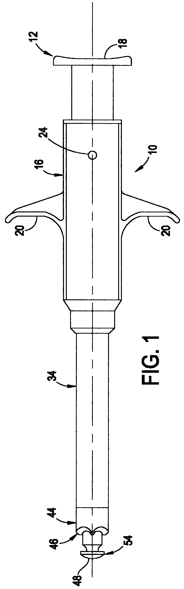
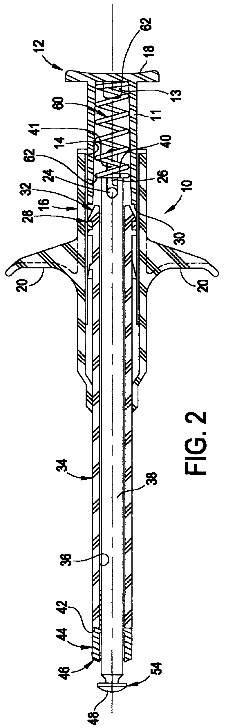
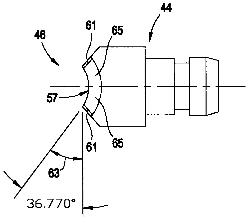
Shown in FIGS. 1 and 2 is a medical punch 10 which is in accordance with an embodiment of the present invention. Instead of having a single cutting edge with effectively no shear angle, the medical punch 10 includes a plurality of cutting edges each having a diminishing shear angle. As a result, the medical punch 10 can be used to achieve a clean and accurate cut of material. Additionally, the medical punch 10 provides that an excessive amount of hand pressure need not be employed to effect the cut. Furthermore, the medical punch 10 does not tend to jam because the material is generally kept centralized with res...
PUM
 Abstract
Description
Claims
Application Information