Thermal printer with a mode changing gear

Inactive Publication Date: 2000-07-04
MITSUBISHI ELECTRIC CORP
View PDF6 Cites 42 Cited by
  • Summary
  • Abstract
  • Description
  • Claims
  • Application Information

AI Technical Summary

Problems solved by technology

Such a thermal printer of the prior art has drawbacks that the thermal printing head 106 separates from the platen roller 110, when the web is wound back.
Further, the thermal printer in the prior art is applicable only to web type paper, and sheet type paper can not be used.

Method used


Image

  • Thermal printer with a mode changing gear
  • Thermal printer with a mode changing gear
  • Thermal printer with a mode changing gear

Examples


Embodiment Construction

1

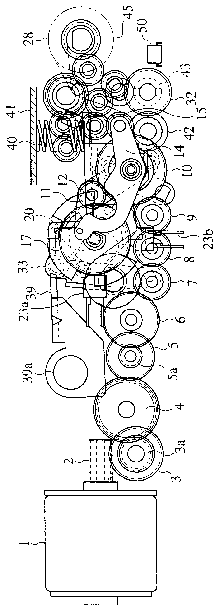
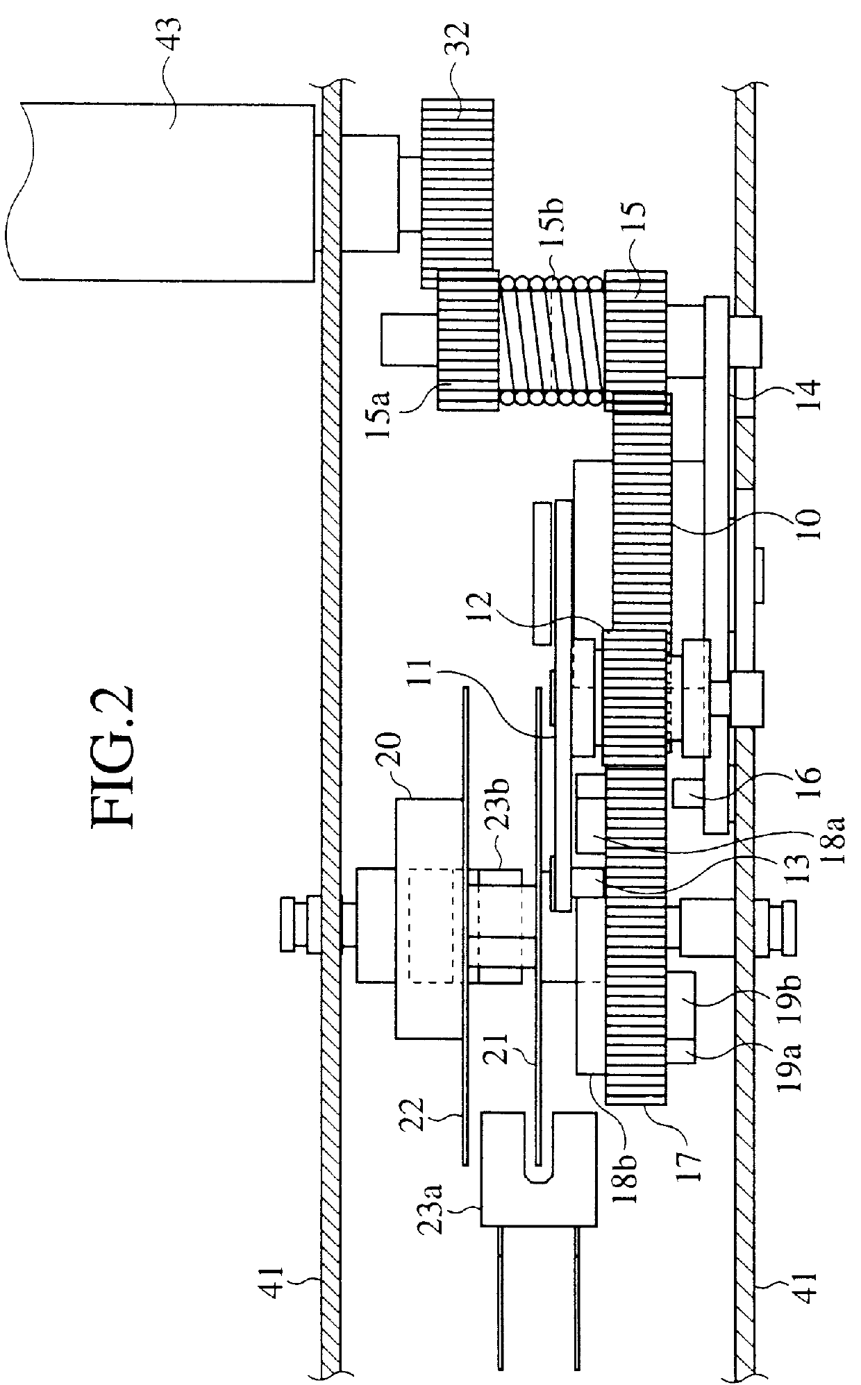
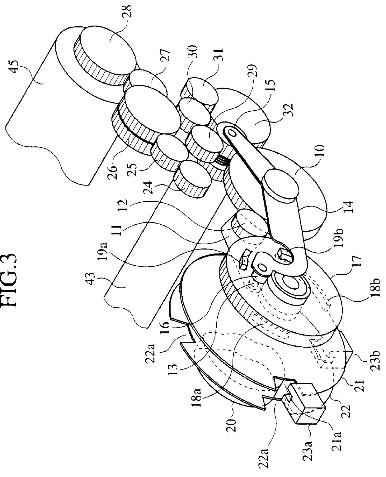
In the figures, reference numeral 1 denotes a motor. A gear 2 is fixed to the shaft of the motor 1. The driving force from the motor is transferred to a sun gear 10 through gears 3 to 9.

A mode exchanging arm 11 is disposed at the rear side of the sun gear 10 and has the same rotation axis as the sun gear 10. A first planet gear 12 is disposed on the mode exchanging arm 11, the planet gear 12 engages with the peripheral gear of the sun gear 10 and moves along the peripheral. A first pin 13, as a projecting portion, is disposed at the tip of the mode exchanging arm 11.

A feeding roller exchanging arm 14 is disposed at the front side of the sun gear 10 and has the same rotation axis as the sun gear 10. A second planet gear 15 is disposed on the feeding roller exchanging arm 14. The second planet gear 15 engages with the peripheral gear of the sun gear 10 and moves along the peripheral. A second pin 16, as a projecting portion, is disposed at the tip of the feeding roller exchanging arm...


PUM


Abstract

A thermal transfer type printer comprising a sun gear 10 connected (indirectly) with a motor 1, exchanging arms 11, 14 having a pin 13,16 respectively, planet gears 12,15, an exchanging gear having bosses 18,19 and engaging with the planet gear 12, a cam 20, a link mechanism 33, and gears 24-32 which engage with the planet gear 15 when the planet gear 15 comes to a predetermined angle position so as to drive a printing paper feeding mechanism 43,44 and to drive an ink ribbon feeding mechanism 45,46. The procedures of the pressing and separation of the thermal printing head, the feeding of the ink ribbon, and the feeding of the paper, can be carried out using only one motor, though not only web type paper but also sheet type paper are usable.

Description

1. Field of the InventionThe present invention relates to a thermal transfer type printer, particularly, relates to a driving system of a thermal transfer type printer, in which, the motion of a thermal printing head to and from the printing paper, the feeding of the printing paper, and the feeding of the ink ribbon are driven by a common motor.2. Description of the Prior ArtJapanese Patent Application JP-A-7-76150 discloses such a driving system of a thermal transfer type printer in the prior art. FIG. 10 is a side view of the driving system of the thermal transfer type printer of the prior art disclosed in it, showing the initial state (a) and the printing state (b).Reference numerals 101 denotes a motor gear connected to a motor (not shown), and the reference numeral 102 denotes a transmission gear group. The transmission gear group 102 includes an intermittent gear 102a engaging with the motor gear 101, a swing-down gear 102b, a swing-up gear 102c, a bracket 102d rotatable aroun...

Claims


Application Information

Patent Timeline
Patent Type & Authority Patents(United States)
IPC IPC(8): B41J23/02B41J23/00B41J33/14B41J33/24B41J29/38B41J2/325B41J25/304
CPCB41J23/025B41J29/38B41J33/24
Inventor SHIMIZU, MASAHIKOFURUKI, ICHIRO
Owner MITSUBISHI ELECTRIC CORP
Why Eureka
Try Eureka