Magnetic decoupler

a magnetic decoupler and tag technology, applied in the field of magnets, can solve the problems of inability to easily remove the tag from an article by a thief, for example, and achieve the effect of preventing th

Inactive Publication Date: 2000-07-04
DEXTER MAGNETIC TECH
View PDF16 Cites 67 Cited by
  • Summary
  • Abstract
  • Description
  • Claims
  • Application Information

AI Technical Summary

Problems solved by technology

As a result, unauthorized removal of the tag from an articl

Method used


Image

  • Magnetic decoupler
  • Magnetic decoupler
  • Magnetic decoupler

Examples


Embodiment Construction

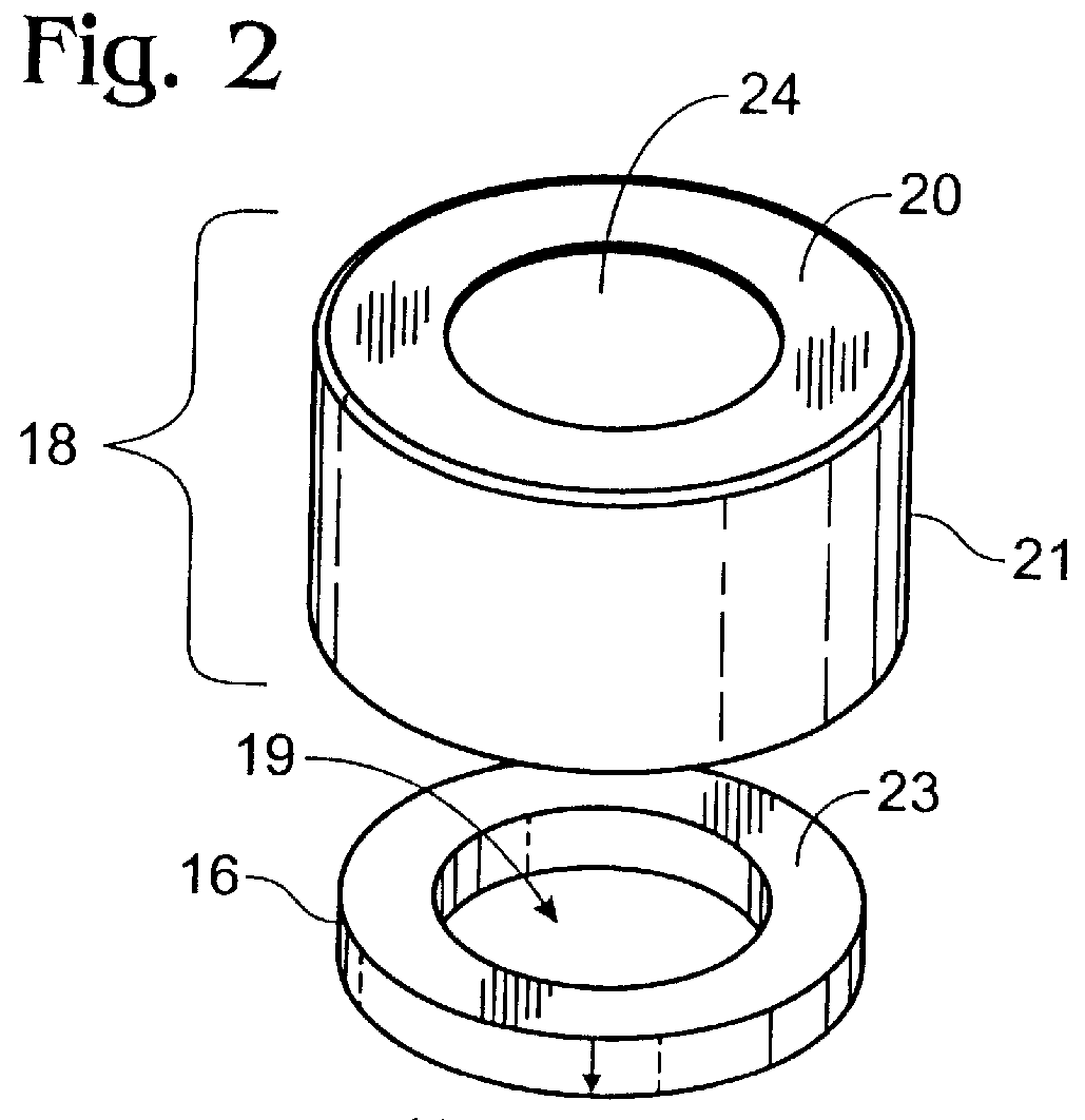
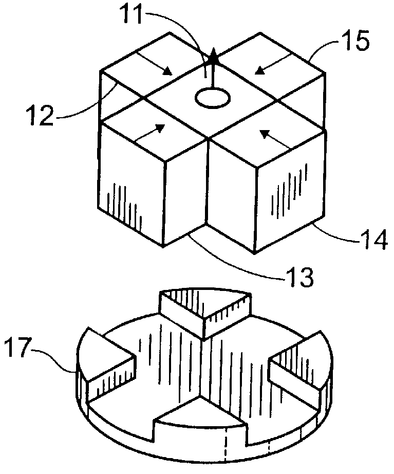
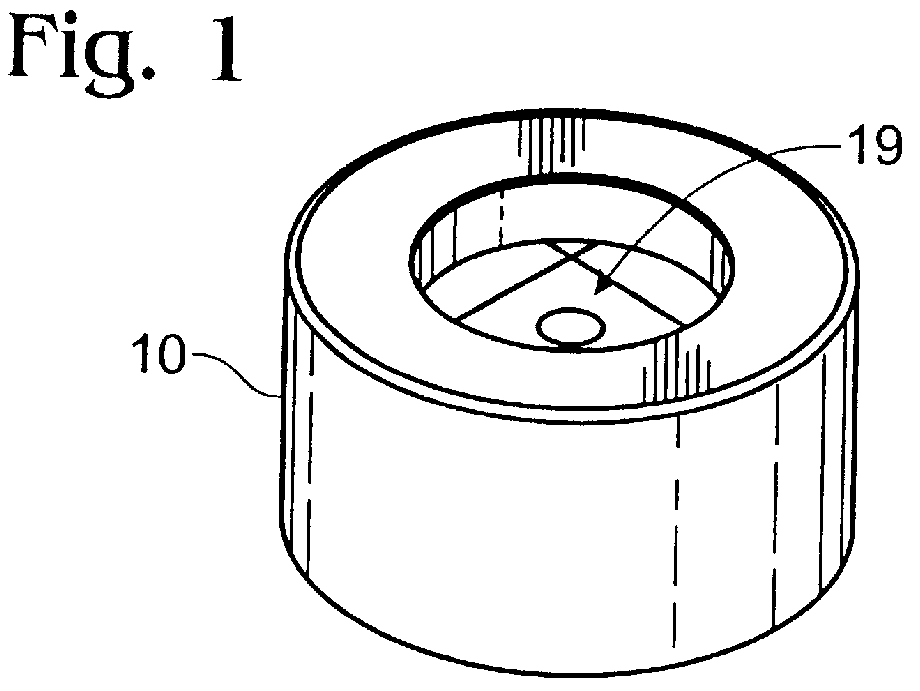
According to the present invention, a powerful permanent magnet structure having an axial magnetic flux density gradient greater than 55 Tesla per meter along the desired flux path is provided. With reference to an embodiment illustrated in FIGS. 1 and 2, one component of the magnet assembly is a high coercivity ring shaped, or annular, permanent magnet 16 having a bore 19 of sufficient diameter to accommodate, e.g., the nipple 34 of a security tag. In one embodiment, the magnet assembly further comprises a cruciform arrangement of powerful high coercivity permanent magnets 11, 12, 13, 14 and 15 with magnetic orientations arranged in "quadrature". Optimum dimensions may be obtained through numerical analysis. However, a working model, described herein, provides outer corners of the magnets in the cruciform magnet assembly that approximate the outer diameter of the annular magnet 16. In an alternative embodiment, the magnets 12-15 may be of trihedral shape, rather than rectangular or...


PUM


Abstract

An improved magnetic decoupler with a magnetic field shape, strength and gradient optimized for releasing security tags, such as an antitheft device of the type described above. Due to the structure of the magnetic decoupler, it contains less ferrous material than prior art decouplers heretofore employed. Reduction in size of the magnetic decoupler, along with improved magnetic strength, derive from the magnet assembly including magnets arranged with orientations that increase axial magnetic field gradient by superposition of the magnetic fields of each magnet.

Description

1. Field of the InventionThe present invention relates generally to magnets and in particular to an improved magnetic decoupler for use with antitheft devices, in which the magnetic decoupler comprises a plurality of magnets arranged with their magnetic orientations orthogonal to each other.2. Description of the Related ArtWith reference to FIGS. 5 and 6, a known antitheft device used, for example, in retail sales stores that sell such goods as clothing or dry goods comprises a security tag, or simply, tag, usually having the shape of a disk or other generally planar shaped object. The tag contains a proprietary material that sets off an alarm, for example, if the goods are removed from the store without first detaching the tag. The tag is commonly attached to the goods by means of a tapered pin. The pin is inserted through the goods and into one side of the tag. The length of the pin is generally greater than the thickness of the tag. The side of the tag opposite that into which th...

Claims


Application Information

Patent Timeline
IPC IPC(8): E05B73/00H01F7/04H01F7/02
CPCE05B73/0017H01F7/0278H01F7/04
Inventor STELTER, RICHARD E.CHOIT, DAVIDDEVANEY, THOMAS J.
Owner DEXTER MAGNETIC TECH
Why Eureka
Try Eureka