
Electromagnetic regulator assembly for adjusting and controlling the current uniformity of continuous ion beams

a technology of ion beams and regulators, applied in the field of adjusting the uniformity of charged particles within ion beams, can solve the problems of difficult implementation in practice, difficult to understand fully or effectively control algorithms, and complex specificities of algorithms

Active Publication Date: 2005-01-27
WHITE NICHOLAS R
View PDF4 Cites 43 Cited by
  • Summary
  • Abstract
  • Description
  • Claims
  • Application Information

AI Technical Summary

Benefits of technology

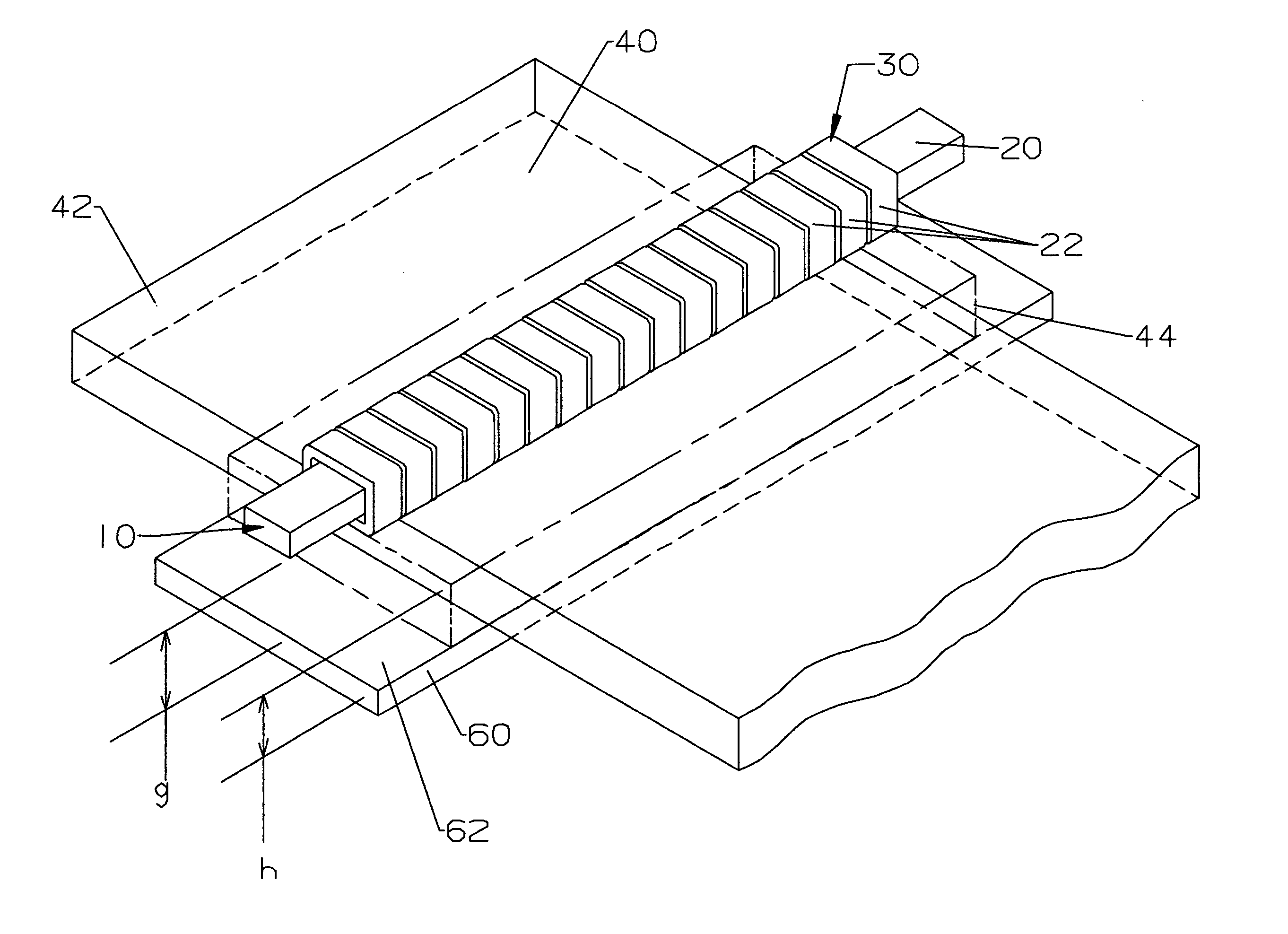
"The present invention provides an improved electromagnetic regulator assembly for adjusting and controlling the uniformity of charged particles in a continuous ion beam. The assembly includes a first linear multipole array and a second linear multipole array, each comprising a straight support rod and an array of wire coils. The wire coils are positioned adjacently on the support rod and are formed of electrically conductive matter. The assembly also includes an on-demand means for passing electrical energy of variable current independently through each wire coil, resulting in the generation of an orthogonally extending magnetic field gradient of limited breadth. A circumscribed spatial passageway is also included for applying a contiguous magnetic field to and adjusting and controlling the magnetic field gradient of an applied contiguous magnetic field for a continuous ion beam. The technical effects of the invention include improved control and adjustability of the charged particles in a continuous ion beam, as well as improved uniformity of the beam."

Problems solved by technology

However, such algorithms are very complicated in their specifics; and are quite difficult to implement in practice as a functional part of an ion implantation system.
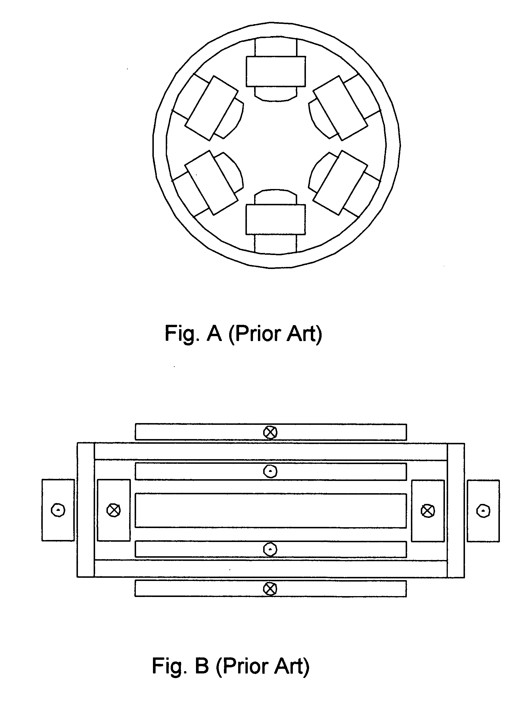
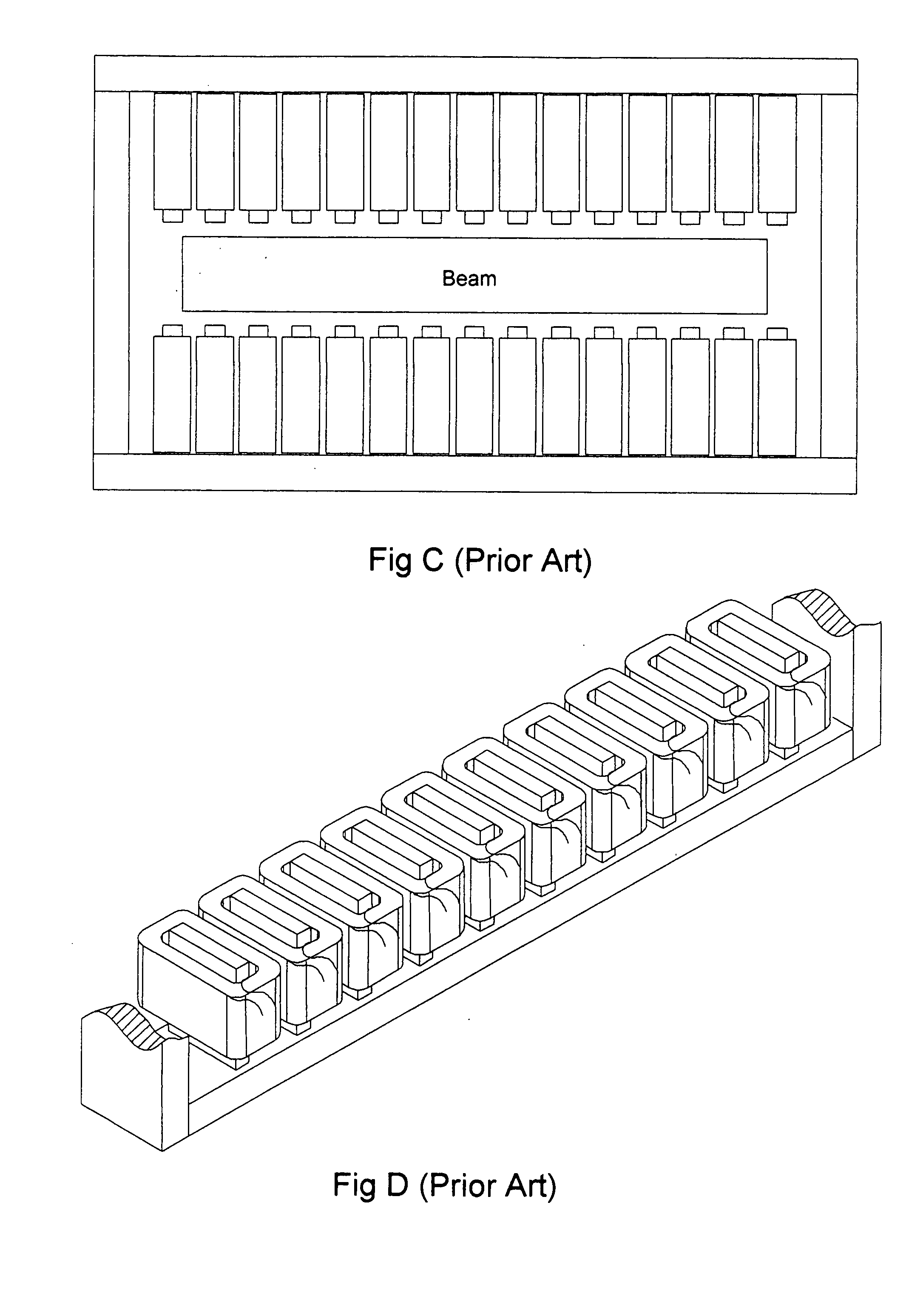
It is noteworthy, however, that the multipole structures within all these known systems all have been designed to provide a magnetic field whose strength is controlled as a function of the x-coordinate / dimension of the flowing ion beam In addition, they often require involved software algorithms to operate; and, in general, are beyond the competence of a modestly skilled operator to understand fully or to control effectively.

Method used


Image

  • Electromagnetic regulator assembly for adjusting and controlling the current uniformity of continuous ion beams
  • Electromagnetic regulator assembly for adjusting and controlling the current uniformity of continuous ion beams
  • Electromagnetic regulator assembly for adjusting and controlling the current uniformity of continuous ion beams

Examples


Embodiment Construction

The present invention is an electromagnetic regulator assembly which can adjust and control the degree of uniformity for charged particles traveling within a continuous ion beam. The invention comprises an article of manufacture and a method for adjusting the concentration of charged particles carried in such continuous ion beams. The instant invention thus provides an effective arrangement and means for controlling the uniformity of the ion current along the transverse direction of ribbon-shaped, continuous beams which are targeted at a plane of implantation or a work surface for the placement of charged ions into a prepared workpiece (such as a silicon wafer), which is passed through the beam orthogonal to its long direction in order to implant the whole of one face of the workpiece.

I. Definitions

In order to avoid inconsistencies in terminology, eliminate ambiguities in denotative and connotative meanings, and to increase the clarity and completeness of comprehension and under...


PUM


Abstract

An electromagnetic regulator assembly for the production of contiguous magnetic fields which are applied to a continuous ion beam is described. The assembly is structured for controlling the uniformity of traveling continuous ribbon-shaped beams; and allows for direct adjustment of the magnetic field gradient of the magnetic field as the parameter for increasing the current uniformity.

Description

FIELD OF THE INVENTION This invention is concerned generally with controlling the uniformity of charged particles within an ion beam. More particularly, the invention is directed to the production of more uniform ribbon-shaped continuous ion beams; provides an apparatus and method for adjusting the current density of charged particles in such continuous beams; and presents an assembly for controlling the current uniformity along one transverse direction of parallel, ribbon-shaped, continuous ion beams which are pointed at a target plane for treating prepared workpieces with charged ions—e.g., an ion implanter for doping silicon wafers or flat-panel display substrates, where the ion beam uniformity must be controlled with great precision. BACKGROUND OF THE INVENTION In the field of processing materials with ion beams, various techniques have been developed for producing large, approximately-parallel ribbon ion beams with controlled current uniformity. In this context, the term ‘con...

Claims


Application Information

Patent Timeline
Patent Type & Authority Applications(United States)
IPC IPC(8): H01J37/141H01J37/147H01J37/317
CPCH01J37/141H01J37/1471H01J37/1472H01J37/3171H01J2237/31703H01J2237/1504H01J2237/152H01J2237/30433H01J37/3172H01J37/317
Inventor WHITE, NICHOLAS R.
Owner WHITE NICHOLAS R
Learn More