Eight-roller type rolling mill and method of rolling using the mill

a mill and eight-roller technology, applied in the field of rolling mills, can solve the problems of troublesome and expensive provision and maintenance of roller sets, time and labor, and inability to meet the needs of profiled rolls of every siz

Inactive Publication Date: 2000-07-11
DAIDO STEEL CO LTD
View PDF8 Cites 17 Cited by
  • Summary
  • Abstract
  • Description
  • Claims
  • Application Information

AI Technical Summary

Problems solved by technology

The two-roller type rolling mills have a drawback that profiled rolls for every sizes are necessary because adjustable size ranges of each roller are small.
Provision and maintenance of the roller sets are troublesome and expensive, and further, changes in the sizes of the steel bars to be p...

Method used


Image

  • Eight-roller type rolling mill and method of rolling using the mill
  • Eight-roller type rolling mill and method of rolling using the mill
  • Eight-roller type rolling mill and method of rolling using the mill

Examples


second embodiment

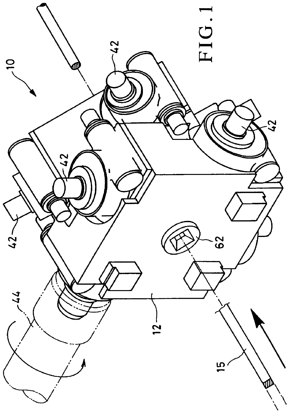
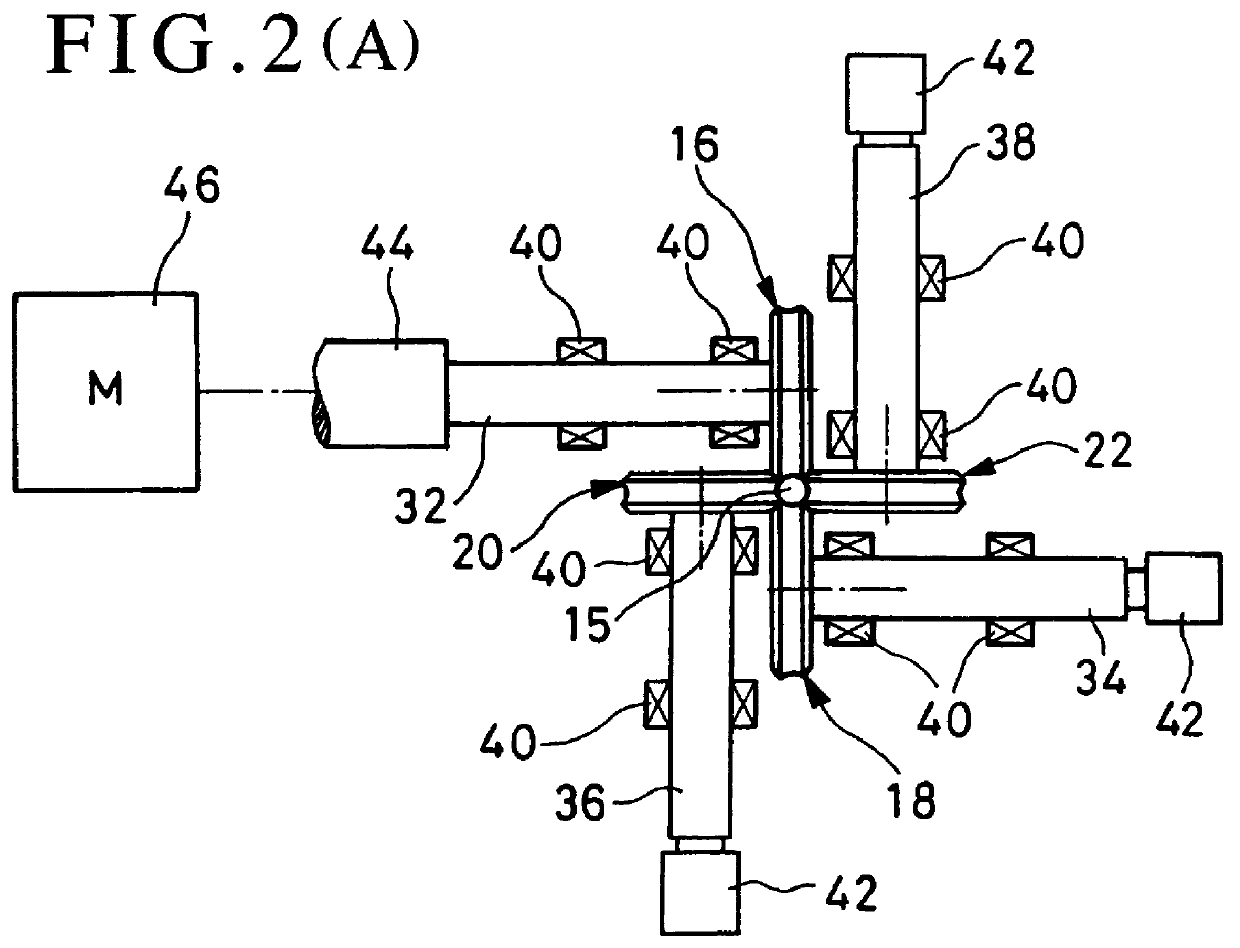
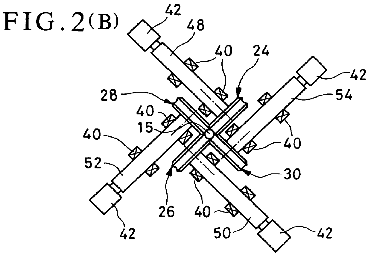
In the invention the eight-roller type rolling mill uses single driving source as the driving source, which drives only one roller of the front four rollers, and the remaining three rollers of the front four rollers and all the four rollers of the back four rollers freely rotate following supply of the material being rolled. This driving system makes it possible to use only one driving source and to simplify the mechanism of transmitting driving force from the driving source to the rollers. Thus, the structure of eight-roller type mill of the invention, which may otherwise be complicated, can be simplified.

In addition, the fact that rotating speeds of the rollers are synchronized with the advancing speed of the material to be rolled surely prevents the material from being compressed or stretched, and therefore, rolled products are of good quality.

third embodiment

the invention uses driving sources of small driving force to idle-rotate the free rotating rollers in the same directions as those under rolling prior to engagement of the material to be rolled by the rollers. This minimizes resistance or shock at engagement of front end of the material by the rollers, particularly, by the back four rollers, so that rolling may proceed smoothly.

After engagement of the material to be rolled, driving force for idle-rotation of the rollers may be removed.

fourth embodiment

In the invention, the rolling mill is provided with, on one hand, a support guide at the inlet of the material to be rolled to the front four rollers, and on the other hand, no guide is provided between the front four rollers and the back four rollers so that the material being rolled is directly passed from the front four rollers to the back four rollers. This guideless system further simplifies structure of the mill. Because of close installation of the front four rollers and the back four rollers in one housing block, the material being rolled is readily transferred from the front four rollers to the back four rollers. The support guide at the inlet to the front four rollers guides the material to be rolled for engagement by the front four rollers.


PUM

PropertyMeasurementUnit
Angleaaaaaaaaaa
Forceaaaaaaaaaa
Diameteraaaaaaaaaa

Abstract

A final finish-rolling stand of a rolling machine for producing round bar material is constructed as an eight-roller type rolling machine comprising: front four rollers of "+" distribution and back four rollers of "X" distribution which are contained in one housing block. Only one driving source is used for the rolling machine, and the driving force from the driving source is transmitted to one roller of the front four rollers to forcibly drive this roller. The remaining rollers are freely rotatable and rotate synchronously with transfer of the material being rolled so as to carry out rolling down of the material. Structure of the rolling machine is simple and adjustable range of sizes of the product is wide.

Description

1. Technical FieldThe present invention concerns a rolling mill and a method of rolling round steel bars and steel wire using the mill.2. Prior ArtAs the rolling mills for producing round steel bars and steel wire there has been generally used two-roller type rolling mills, in which a pair of rollers oppositely disposed in parallel directions, and the peripheries of the rollers are pressed onto the materials to be rolled so as to roll and elongate them into predetermined sizes.Such rolling steps using the two-roller type rolling mills are as illustrated in FIG. 7.The Figure shows an example of round-oval type rolling. According to the conventional technology, as illustrated in the Figure, a material to be rolled 200 is sequentially rolled with rollers 202 to form alternative sections of oval-round-oval-round, and in the final finish-rolling step the material is shaped into round bars or wires of desired sizes.The two-roller type rolling mills have a drawback that profiled rolls for ...

Claims


Application Information

Patent Timeline
IPC IPC(8): B21B35/00B21B35/04B21B1/16B21B1/18B21B13/00B21B13/12B21B31/16B21B35/10B21B31/26B21B27/02B21B13/10B21B31/02
CPCB21B1/18B21B13/12B21B35/04B21B13/005B21B31/26B21B35/10B21B2035/005
Inventor SUDA, HIROSHITAJIMA, TATSUO
Owner DAIDO STEEL CO LTD
Why Eureka
Try Eureka