Method for compound movement of an aeration unit

a technology of aeration unit and compound movement, which is applied in the direction of carburetor air, filtration separation, separation process, etc., can solve the problems of aeration operation, affecting the operation of the aeration unit, and the removal of the pipes for maintenance is difficult, if not impossible, and achieves the effect of convenient and safer access

Inactive Publication Date: 2000-07-11
MEURER RES
View PDF12 Cites 4 Cited by
  • Summary
  • Abstract
  • Description
  • Claims
  • Application Information

AI Technical Summary

Benefits of technology

In the various examples noted above, the second motion of the compound motion may be provided by structure on the two or more beams to which the primary forces are applied. Such structure defines a platform. The platform mounts guides, such as a drawer guide. A drawer fixed to pipes of an aeration unit moves along the drawer guide with the aeration unit perpendicular to the first motion, for example. Such perpendicular motion is horizontal when the first motion of the beams and the aeration unit (with its pipes) is vertical. The horizontal m

Problems solved by technology

Thus, removal of the pipes for maintenance is difficult, if not impossible, without interrupting the aeration process.
In prior aeration units with removable pipes, the individual pipes and valves are generally difficult to handle.
Such hoists or cranes often interfere with the aeration operations, and do not provide an easy way of repositioning the supports on the bottom so as to assure that the pipes of the aeration units are level during aeration operations.
Further, the many different types of aeration units do not lend themselves to a universal, or all-purpose, way of retrieving the units from a basin for maintenance, and of replacing the units in the basin after maintenance with assurance that the pipes of the aeration unit will be level.
The extension of the main band across the coping of the basin, and such separate truss, may interfere with operations other than aeration.
However, opposite ends of the cable exit the basin at opposite sides of the basin, such that there is no central point at which the cable is moved.
Further, the pipe can onl

Method used


Image

  • Method for compound movement of an aeration unit
  • Method for compound movement of an aeration unit
  • Method for compound movement of an aeration unit

Examples


embodiment 31-3 (fig.9g)

In embodiment 31-3 (FIG. 9G), the quadrilateral frame 48-Q has the corner 53Q defined between one module 36-1 and a second module 36-2 at right angles to the module 31-1. Also, a third module 31-3 extends diagonally across from the corner 53Q to a corner 53-3. Preferably, the diagonal of the third module 36-3 includes a compression member 38. Based on the description of the one module 36 above in re FIG. 9A, it may be understood that in embodiment 31-3 one third of the primary force F.sub.P is transferred from the corner 53Q into each of the three modules 36-1, 36-2 and 36-3, to the respective corners 53-1, 53-2 and 53-3. Each such corner 53-1, 53-2, and 53-3 is moved as the primary force F.sub.P moves the proximal end 37 of each such module 36-1, 36-2, and 36-3.

embodiments 31-c

Compound Movement Embodiments 31-C

The compound movement embodiments 31-C of the present invention include many of the same features as those described in the above-identified parent application. Those features are described below using the same reference numbers as are used above.

Service Area 34

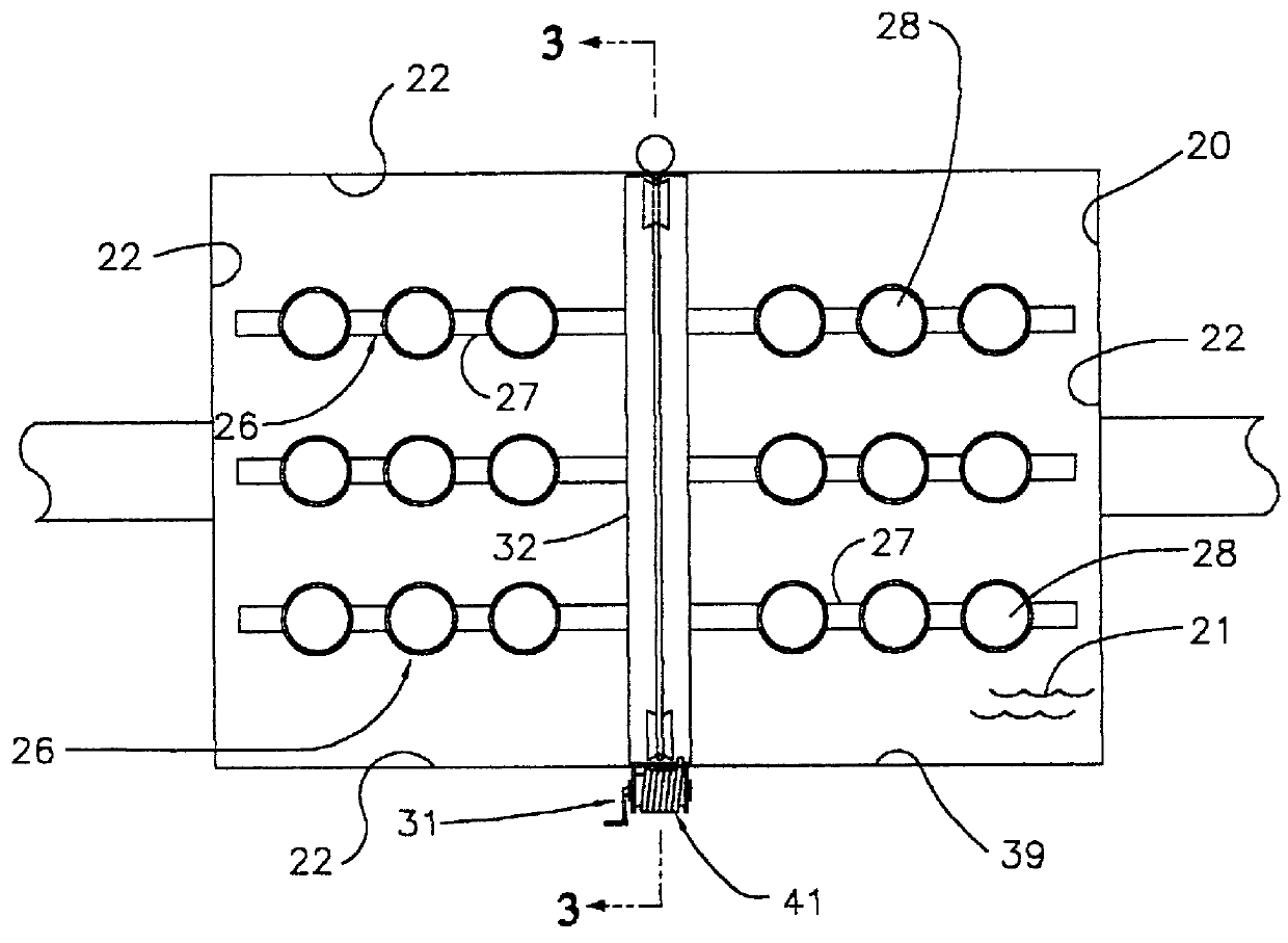
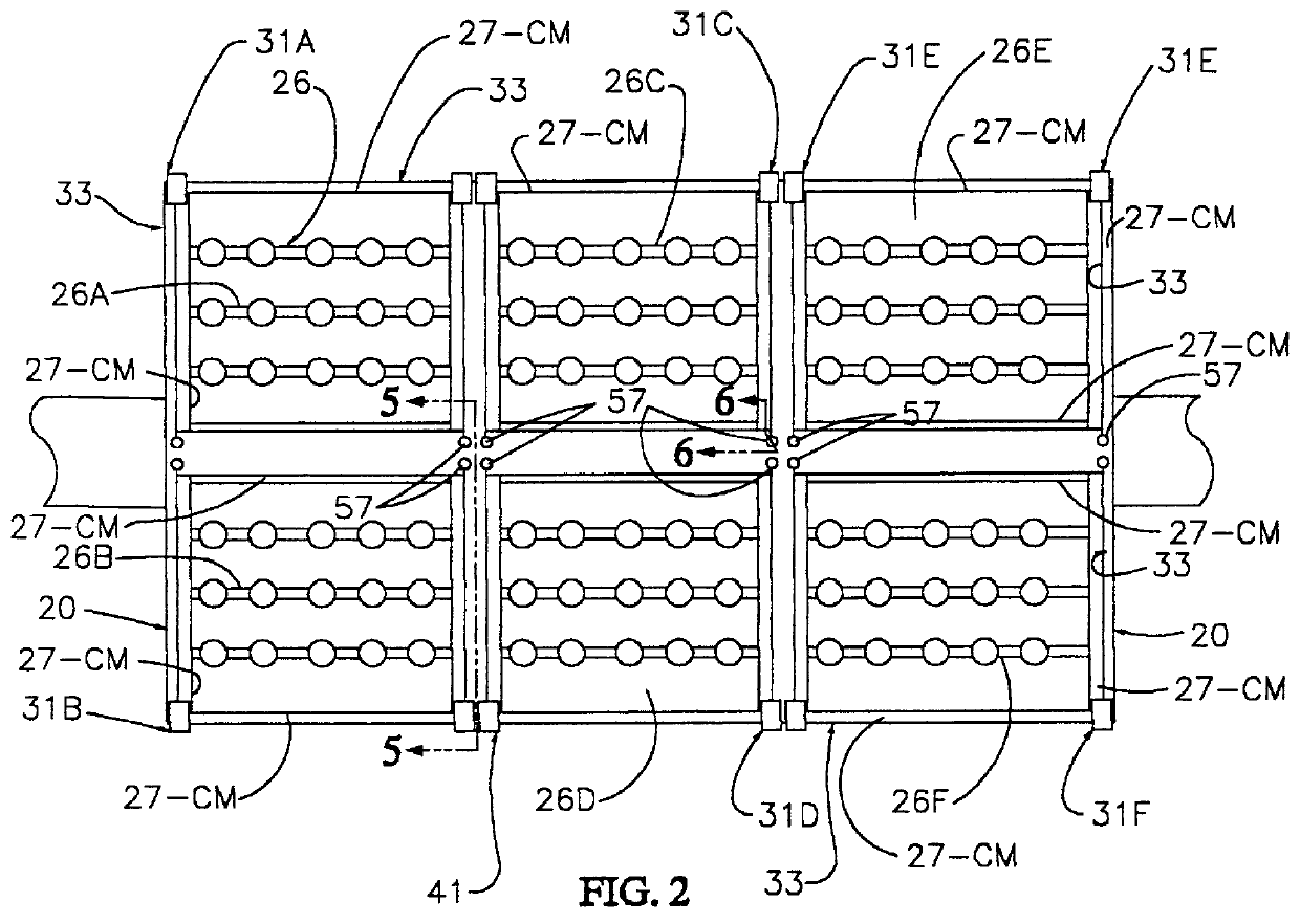
Referring to FIGS. 13A and 20, the basin 20 is provided with the near side 39 at which service personnel (not shown) operate the drive 41 (FIG. 13A). The service area 34 is provided as an area adjacent to the basin 20 on which the service personnel may work. In one aspect of such work, an aeration unit section 26A may simply be carried from the basin 20 over (or across) the service area 34 to another facility (not shown) for servicing. In another aspect of such work, the aeration unit section 26A may be serviced while over (or resting on) the service area 34. For either type of work, for example, the service area 34 may extend from the near side 39 away from the basin 20 for a distance SAL th...

embodiment 31-c-v

Compound Movement Embodiment 31-C-V / D

Second Movement

As described above, the service area 34 adjacent to the near side 39 of the basin 20 is dimensioned to provide room for service personnel to move around a section of the aeration unit 26 (e.g., the section 26A) when that section 26A has been moved over the service area 34. Such movement of the section 26A to the position over the service area 34 represents the second of the compound movements. The elements which provide such second movement are first described with reference to FIGS. 13A-13C. There, the truss 93 forms the compression members 38 and supports lateral beams 96. The lateral beams 96 extend in the direction of a width W of the basin 20 and are secured to the truss 93. The lateral beams 96 are provided with guides 97 which may directly or indirectly engage the pipes 27 to guide the second of the compound movements of the pipes 27.

In FIGS. 13A-13C the guides 97 are shown in the form of opposed channels 101. Each of the op...


PUM

PropertyMeasurementUnit
Forceaaaaaaaaaa
Areaaaaaaaaaaa

Abstract

Improvements are made to a system in which force is applied to aeration units from only one side of a basin. Part of such force is vector transferred from one end of a beam of the aeration unit to the other end of the beam to move both ends of the beam. The beam supports pipes of the aeration unit. A force transfer module includes one force transfer strand held in a force transfer path between fixed opposite ends of the strand. The force transfer path extends in part along the beam, which is placed in compression. Motion of the one end of the beam resulting from the force is transferred by the single force transfer strand to the opposite end of the beam so that both ends of the beam move relative to the basin under the action of the force. The improvements include guides on the beam for allowing the pipes of the aeration unit to move off the beam to a side of the basin for servicing, a levelling device for positioning ends of the pipes level with each other to enable the pipes to introduce uniform amounts of gas into the basin, and a plurality of vector force transfer modules provided across the basin to apply forces to the beam at many locations.

Description

1. Field of the InventionThis invention relates to providing compound movement of an aeration unit, and more particularly, to first applying a primary force to an aeration unit of a water treatment apparatus to remove the aeration unit from the water treatment apparatus, and to second applying a secondary force to the aeration unit to move the entire aeration unit over a service area adjacent to the water treatment apparatus to facilitate servicing the aeration unit.2. Discussion of Prior Aeration Unit MoversBasins are used to purify liquids in facilities such as water and waste water treatment plants by removing impurities, thereby making the water suitable for use, reuse, or for further treatment. Aeration units are used in basins of the plants to provide gas for biological treatment, or for mixing the liquid. The aeration units are usually permanently installed in the basin. In many permanent installations, the pipes of the units are secured to the bottom of the basin to resist t...

Claims


Application Information

Patent Timeline
IPC IPC(8): B01F3/04
CPCB01F3/04113B01F2003/04234Y10S261/70B01F23/23105B01F23/23116
Inventor BRAUCH, JOSEPH KARLMEURER, CHARLES LONNIEMEURER, DOUGLAS LEE
Owner MEURER RES
Why Eureka
Try Eureka