Antiskid control apparatus

a control apparatus and anti-skid technology, applied in the direction of brake systems, vehicle components, brake components, etc., can solve the problems of limited movement of the brake pedal during anti-skid control, deterioration of speed sensors, and difficulty in detecting wheel slip states, so as to increase the brake pressure pressure-increasing operations, and improve the brake-pedal operation

Inactive Publication Date: 2000-07-18
DENSO CORP
View PDF20 Cites 11 Cited by
  • Summary
  • Abstract
  • Description
  • Claims
  • Application Information

AI Technical Summary

Benefits of technology

Since the brake-pressure adjusting unit increases the brake pressure by using a hydraulic pressure generated by the master cylinder, the number of operations to increase the brake pressure per unit time is well reflected in the time period spent on the movement of a predetermined stroke of the brake pedal. The present invention controls the amount of time for the brake pedal to be within a predetermined stroke range, thus improving the brake-pedal operation.
When an antiskid control apparatus uses the master cylinder as a sole pressure source, fluid flowing from the master cylinder is supplied unmodified for increasing a brake pressure applied to a wheel. When there is no need to increase the brake pressure, the flow of fluid from the master cylinder is stopped. Thus, the operation carried out by the brake-pressure-adjusting unit to increase the brake pressure is directly related to the movement of the brake pedal. According to the present invention, since the number of operations to increase the brake pressure per unit time is adjusted to a proper value, the effect of the number of operations adjusted to a proper value can be directly observed as a brake-pedal operation feedback to the driver.
Preferably, the brake-pressure-adjusting unit adjusts the brake pressure by increasing the brake pressure using 1.5 to 3.5 pressure-increasing operations per second. These values are transformed into movement speeds of a brake pedal employed in an ordinary vehicle as the range 3 to 7 mm / sec. The values of the movement speeds result in a very good brake-pedal operation feedback.
Preferably, the brake-pressure adjusting unit gradually increases the brake pressure pressure-increasing operations per second when a slip state of a wheel is small and decreases or maintains the brake pressure when the slip state is large. In order to make the pressure increasing adjustment of the brake pressure more effective, when increasing the brake pressure, the number of consecutive pressure-increasing operations carried out so far by the brake-pressure adjusting unit is counted and the increase in brake pressure resulting from one pressure-increasing operation is adjusted so that the counted number of consecutive operations is within the predetermined range. In this way, a very good braking force is obtained which shortens the required braking distance.

Problems solved by technology

However, it is difficult to detect slip states of wheels at low speeds because the accuracy of signal detection by wheel speed sensors deteriorates.
In the antiskid control unit described above, however, movement of the brake pedal during antiskid control is restricted because the brake-pressure adjusting unit increases the brake pressure by using the hydraulic pressure generated by the master cylinder and decreases it while cutting off the conduit connected to the master cylinder.
As a result, a driver feels an abrupt difference in the sensitivity of the brake pedal and in the force required to operate the brake pedal.
Therefore, at low speeds, the feedback to the driver from application of the brake is unacceptable because it is not consistent through non-antiskid control and antiskid control.
In addition, typically the restriction on the movement of the brake pedal during antiskid control causes the brake pedal to move a predetermined length only after a certain amount of time.
This causes awkward feedback to the driver who feels that he or she cannot depress the brake pedal because the pedal hardly moves.

Method used


Image

  • Antiskid control apparatus
  • Antiskid control apparatus
  • Antiskid control apparatus

Examples


first embodiment

As shown in Table 2, the A and B pulse patterns are the same as those shown in Table 1 for the As for the C pulse pattern, KU=0 ms, KH=100 ms and N=20 p. That is, no pressure increasing output is provided and a pressure holding output to maintain the hydraulic pressure is provided continuously for 2 seconds (=100 ms.times.20).

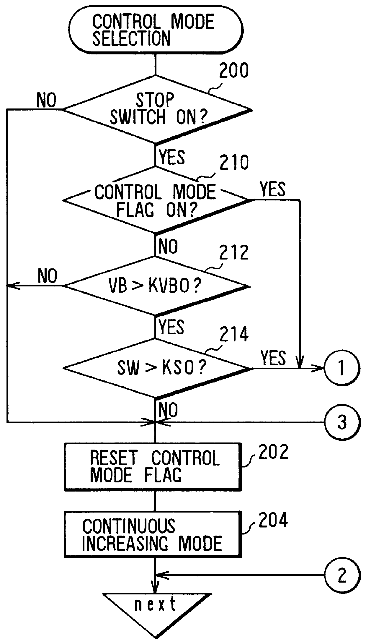
In the course of antiskid control, much like the first embodiment, when the vehicle speed VB becomes equal to or lower than the predetermined value KVB1 (VB.ltoreq.KVB1), resulting in a NO determination at step 222 of the flowchart shown in FIG. 4 or the slip ratio SW becomes equal to or smaller than the predetermined value KS1 (SW.ltoreq.KS1), resulting in a NO determination at step 224 of the same flowchart, the flow of processing may go on to the step 234 by way of step 232. In this case, the processing in a pulse pressure increasing mode shown in FIG. 9 is carried out. If the vehicle speed VB is found to be higher than the predetermined value KVB1 (VB>KVB1...

second embodiment

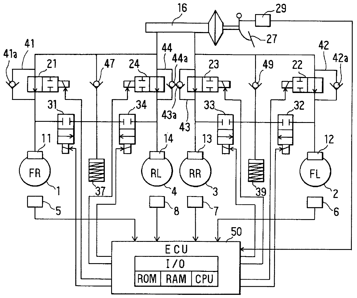
In the second embodiment, however, if the vehicle speed VB is found to be equal to or lower than the predetermined value KVB1 (VB.ltoreq.KVB1) at step 500, that is, if the determination at step 500 is NO, the flow of processing goes on to step 540. In step 540, it is determined whether or not the wheel being controlled is either one of the front right wheel 1 and the front left wheel 2. If the wheel being controlled is either one the front right wheel 1 and the front left wheel 2, the flow of processing proceeds to step 560 which sets the B pulse pattern of the pulse pressure increasing mode and then returns to the main routine. If the wheel being controlled is either the rear right wheel 3 or the rear left wheel 4, the flow of processing proceeds to step 580 which sets the C pulse pattern of the pulse pressure increasing mode and then returns to the main routine. With the control scheme described above, the way of increasing the brake pressures applied to the front right wheel 1 an...

third embodiment

When the interval between the successive pressure increasing outputs is made constant as described in the third embodiment, no processing to adjust the intervals to a proper value is needed. However, the adjustment of the value of TUP is the only means to keep up with variations such as changes in slip ratio SW, changes in force of stepping on the brake pedal and changes in road-surface conditions. That is, when the brake-pressure adjusting unit is used for gradually increasing the brake pressure with a predetermined frequency which is a value within a predetermined range per unit time, the significance of the pressure increasing amount adjusting unit is enhanced.

In addition, in the case of the third embodiment, the pulse pattern of a pulse pressure increasing mode is divided into a first-half pulse pattern and a latter-half pulse pattern. It should be noted, however, that a single fixed pattern can be provided for the entire period of the pulse pressure increasing mode. In the case...


PUM


Abstract

In an antiskid control apparatus, brake pressures of a plurality of wheels are increased by using a hydraulic pressure generated by a master cylinder. When the running speed of a vehicle becomes lower than predetermined value due to a braking operation, a brake-pressure adjusting unit increases the brake pressures applied to the plurality of wheels with timings different from each other. In this way, it is possible to reduce changes with time in amount of fluid flowing out of the master cylinder.

Description

BACKGROUND OF THE INVENTION1. Field of the InventionThe present invention relates to an antiskid control apparatus for controlling the slip of a wheel which occurs upon application of the brake in a vehicle. To be more specific, the present invention relates to an antiskid control apparatus for increasing brake pressure by using a hydraulic pressure generated by a master cylinder.2. Description of the Related ArtA conventional antiskid control apparatus comprises a slip-state detecting unit for detecting slip states of wheels during braking, a master cylinder for generating a hydraulic pressure according to the application of the brake pedal and a brake-pressure adjusting unit for increasing and decreasing brake pressure applied to the wheels so that slip states detected by the slip-state detecting unit are controlled to predetermined states. The brake-pressure-adjusting unit increases the brake pressure by using the hydraulic pressure generated by the master cylinder. Due to this s...

Claims


Application Information

Patent Timeline
Patent Type & Authority Patents(United States)
IPC IPC(8): B60T8/58B60T8/40B60T8/32B60T8/34
CPCB60T8/32B60T8/34B60T8/40B60T8/58B60T8/17616B60T8/17636B60T8/4275B60T8/1761B60T8/171
Inventor WATANABE, TAKASHI
Owner DENSO CORP
Why Eureka
Try Eureka