Check patentability & draft patents in minutes with Patsnap Eureka AI!

Numerical control apparatus for a machine tool

Inactive Publication Date: 2000-08-22
MITSUBISHI ELECTRIC CORP
View PDF37 Cites 55 Cited by
  • Summary
  • Abstract
  • Description
  • Claims
  • Application Information

AI Technical Summary

Problems solved by technology

Because conventional NC apparatus for machine tools are constructed as mentioned above, they have problems that they require changing the contents of their databases in advance for reflecting the know-how possessed by skillful workers on the automatic determination, since they have respectively only one tool and machining condition data memorizing means, which is the basis of the automatic determination, or even if they have plural memorizing means, each of the memorizing means is a division of one memorizing means in contents, and that if the contents of the databases have been changed in advance, when the automatic determination based on standard data having no know-how is contrarily wanted, it is needed to restore the original data to the databases again.
Furthermore, although the machining conditions are automatically determined, they are determined in conformity with single algorithm, then there is a problem that if there exist working objects or tools not supposed at the beginning, it is impossible to select the optimum machining conditions, in such a case the optimum conditions are sometimes selected by the experiences and the perceptions of skillful workers, but not everybody can do the operations and it is impossible to select the strictly optimum or quasi-optimum machining conditions in this case also.
Furthermore, the conventional NC apparatus for the machine tool display the working paths of their tools on the display screens of their display units, transforming and executing correction processes from the beginning to the end in the order, and consequently, it is possible to recognize the working paths of their tools in conformity with the entire NC programs, but it is impossible that an operator makes them display only a local working path to a certain working region.
Moreover, because the conventional NC apparatus for the machine tool do not memorize the displayed working path data of tools and have not means for identifying the correspondences with their NC programs, the operator who wants to modify the displayed working path data of tools or the visible outlines of working regions has to judge which portions of the NC programs the working paths of tools or the visible outlines of working regions wanted to be modified correspond to the working path data, and has to modify the NC programs after that.
Consequently the conventional NC apparatus for a machine tool have a problem that the efficiency of the operations of making up NC programs is bad.

Method used


Image

  • Numerical control apparatus for a machine tool
  • Numerical control apparatus for a machine tool
  • Numerical control apparatus for a machine tool

Examples


embodiment 2

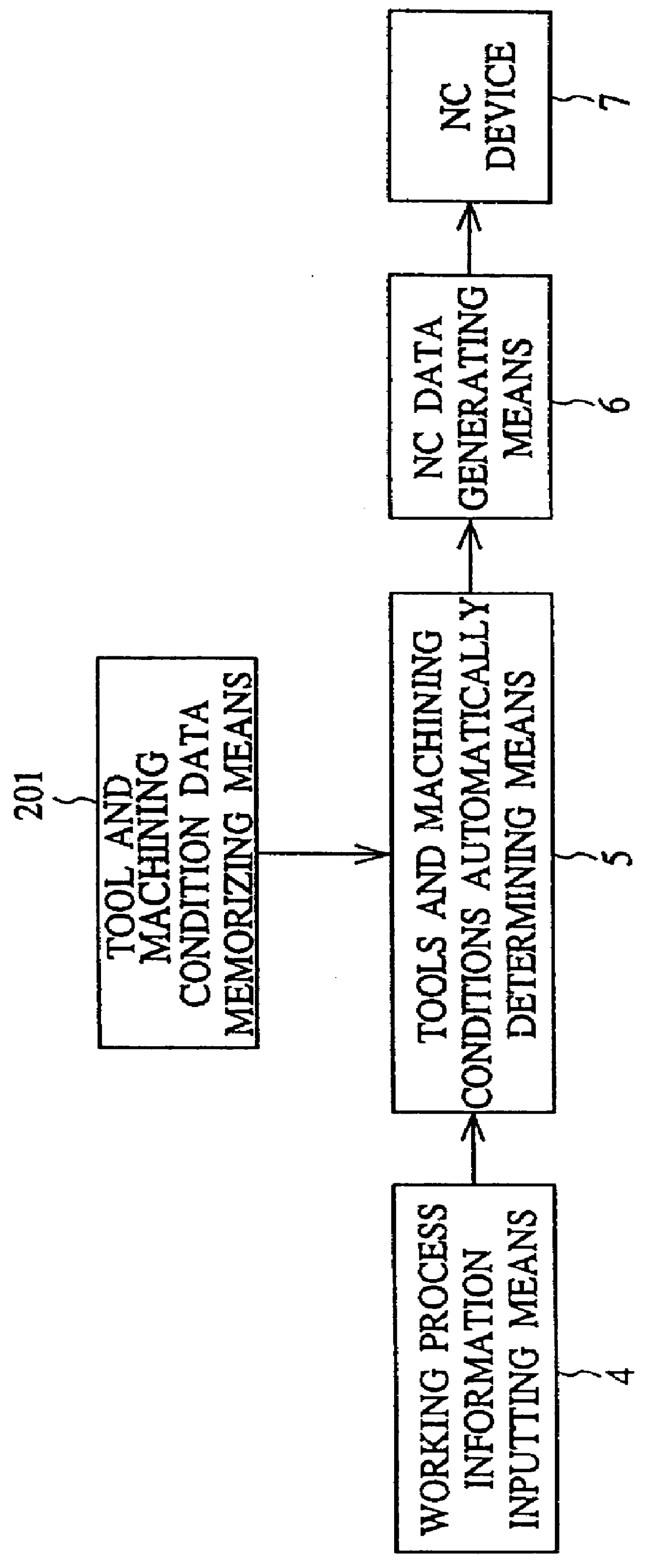
FIG. 6 illustrates a block diagram showing an NC apparatus for a machine tool of an embodiment of the invention. In FIG. 6, reference numeral 11 designates a tool and machining condition memorizing means (or standard database), reference numeral 12 designates a customized tool and machining condition memorizing means (or user's own database), reference numeral 3 designates an input device, reference numeral 4 designates a working process information inputting means, reference numeral designates a tool and machining condition automatically determining means, reference numeral 6 designates an NC data generating means, and reference numeral 7 designates an NC device. The customized tools and machining conditions mean the tools and the machining conditions personally inputted, or edited after the automatic determination, by a user or a worker.

For instance, supposing that the NC machine tool equipped with this NC apparatus has a large mechanical horsepower, and that the cutting efficienc...

embodiment 3

FIG. 7 illustrates a block diagram of an NC apparatus for a machine tool of an embodiment of the invention. In FIG. 7, reference numeral 1 designates a standard database, reference numeral 2 designates a user's own database, reference numeral 4 designates a working process information inputting means, reference numeral 5 designates a tool and machining condition automatically determining means, reference numeral 6 designates an NC data generating means, reference numeral 7 designates an NC device, reference numeral 21 designates a database managing means re-determining the data of tools and machining conditions having been determined before the modification in accordance with the modified data, and reference numeral 22 designates a data editing means modifying the data in the databases. In addition to them, there is equipped a display unit (not shown) displaying the contents of the aforementioned standard database 1 and the aforementioned user's own database 2 during making up NC pr...

embodiment 4

FIG. 9 illustrates a block diagram of an NC apparatus for a machine tool of an embodiment of the invention. In FIG. 9, reference numeral 1 designates a standard database, reference numeral 2 designates a user's own database, reference numeral 4 designates a working process information inputting means, reference numeral 5 designates a tool and machining condition automatically determining means, reference numeral 6 designates an NC data generating means, reference numeral 7 designates an NC device, reference numeral 31 designates a database editing means modifying the data of the standard database 1 or the user's own database 2, and reference numeral 32 designates a contradiction checking means checking a contradiction between newly registered data and the existing data in case of renewing the data of the user's own database 2 or the standard database 1, and displaying the contradicting contents on the display unit in case of judging that there are contradicting data.

Next the operati...


PUM


Abstract

A numerically controlled apparatus for a machine tool has a tool and machining condition automatically controlling function, and stores standard data of tools and machining conditions in a standard database. The input device of the apparatus inputs the users data of tools and machining conditions other than the contents of the standard database, and the apparatus stores the data inputted with the input device in one or more user databases. The tool and machining condition automatically determining function of the apparatus determines tool and machining condition data by utilizing both of the standard database and one or more the user databases.

Description

1. Field of the InventionThis invention relates to a numerically controlling apparatus for a machine tool comprising the function of automatically determining tools and machining conditions and the function of displaying and editing tool paths. (Hereinafter, terms concerning numerical control such as "numerically controlling", "numerically controlled", of course "numerical control" itself, and so forth are collectively denoted by "NC" for short.)2. Description of the Prior ArtFIG. 1 illustrates a summarized block diagram of a conventional NC apparatus for the machine tool shown in, for example, Japanese Unexamined Patent Applications Published under No. 188249 / 89 (Hei. 1), No. 138504 / 92 (Hei. 4), No. 234135 / 89 (Hei. 1), No. 122524 / 92 (Hei. 4), and the like. In FIG. 1, reference numeral 201 designates a tool and machining condition data memorizing means, reference numeral 4 designates a working process information inputting means, reference numeral 5 designates a tools and machining ...

Claims


Application Information

Patent Timeline
IPC IPC(8): G05B19/4068G05B19/4093G05B19/408G05B19/406B23Q15/00
CPCG05B19/4068G05B19/408G05B19/40937G05B2219/35522G05B2219/36284Y02P90/02
Inventor OUCHI, SADAMIKAMIYA, TAKASHINODA, AKIOTSUJIDO, YOSHINORI
Owner MITSUBISHI ELECTRIC CORP
Features
  • R&D
  • Intellectual Property
  • Life Sciences
  • Materials
  • Tech Scout
  • Unparalleled Data Quality
  • Higher Quality Content
  • 60% Fewer Hallucinations
Learn More