Independently pivotable drivewheel for a wheeled chassis

a technology of independent pivoting and drivewheel, which is applied in the direction of electric propulsion mounting, wheelchair/patient conveyance, transportation and packaging, etc., can solve the problems of additional drives and transmissions, complicated mechanical parts of the steering mechanism of prior art devices, and restricted movement of the drivewheel

Inactive Publication Date: 2000-08-29
MADWED ALBERT
View PDF21 Cites 101 Cited by
  • Summary
  • Abstract
  • Description
  • Claims
  • Application Information

AI Technical Summary

Problems solved by technology

In addition, the movement of the drivewheels is restricted by the linkage to the central steering unit.
Therefore, the mechanical portions of the steering mechanisms for these prior art devices are necessarily quite intricate and complex.
Although the inclusion of such separate and additional drives and transmissions increase the maneuverability of the wheeled chassis, these additional drives and transmissions also add appreciably to the production and maintenance costs of these devices.

Method used


Image

  • Independently pivotable drivewheel for a wheeled chassis
  • Independently pivotable drivewheel for a wheeled chassis
  • Independently pivotable drivewheel for a wheeled chassis

Examples


Embodiment Construction

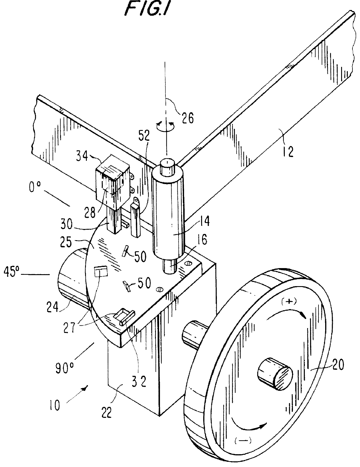
The present invention is directed to an independently pivotable drivewheel for a wheeled chassis such as a motorized wheelchair. The wheeled chassis may, by way of example, comprise the wheeled chassis disclosed in U.S. Pat. No. 5,547,038, the entire contents of which are expressly incorporated herein by reference. Of course, instead of the wheeled chassis disclosed in U.S. Pat. No. 5,547,038 it should be understood that the wheeled chassis may be constructed to include a frame of any suitable shape, including ovoids, as may be necessary or appropriate for a particular application. In addition, one skilled in the art will be able to select the proper materials for the frame which may include, by way of non-limiting example, steel, hard plastics, wood, depending on the particular structure and the application involved.

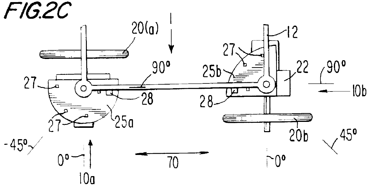
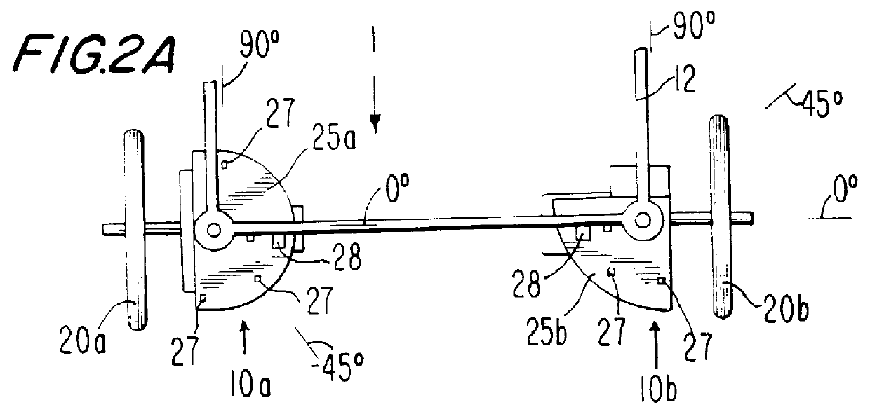
Referring to FIG. 1, a drivewheel assembly 10 in accordance with the invention and including a drivewheel 20, a gearbox 22, and a variable speed, bidirectional drive mo...


PUM


Abstract

A drivewheel assembly is connectable between a frame of a wheeled chassis and a drivewheel, and provides powered rotation for operatively moving the frame and chassis in a user-controllable direction along an underlying supporting surface and for selectively reorienting the drivewheel to change the direction of movement of the frame and chassis along the supporting surface. A motor connected to the drivewheel and operable to rotate the drivewheel is mounted to the frame for pivotal rotation relative to the frame about an orienting axis substantially perpendicular to the drivewheel axis of rotation. In a first operating mode of the drivewheel assembly the motor is coupled to the frame so as to prevent pivotal rotation of the motor about the orienting axis and maintain the current orientation of the drivewheel, whereby operation of the motor to rotate the drivewheel causes the frame and chassis to move along the supporting surface in a direction determined by the current orientation of the drivewheel. In a second operating mode of the drivewheel assembly the motor is decoupled from the frame so as to permit pivotal rotation of the motor about the orienting axis, whereby operation of the motor to rotate the drivewheel causes the motor to pivotally rotate about the orienting axis and thereby effects reorientation of the drivewheel for movement of the frame and chassis in a different direction determined by the reoriented drivewheel.

Description

The present invention relates to drive wheels for a motorized wheeled chassis, particularly to independently pivotable drivewheels mounted at two corners of a generally rectangular chassis equipped with a controller for pivoting and driving each of the drivewheels to enable omnidirectional travel of the wheeled chassis.A conventional motorized wheelchair is typically equipped with a chassis having front wheels implemented by a pair of free-spinning casters and rear wheels in the form of a pair of motor operated wheels which are fixed to the chassis and are frequently driven independently of one another by reversible, variable-speed DC motors. In such wheelchairs, the rotative direction and speed of each of the right and left motor-operated wheels are varied by reversing the power source connection to the appropriate DC drive motor and by regulating the input voltage to the motor, which actions result respectively in switching of the direction of movement of the wheelchair (between f...

Claims


Application Information

Patent Timeline
Patent Type & Authority Patents(United States)
IPC IPC(8): B60K17/00B60K17/30B62D7/06A61G5/04B60K7/00
CPCB60K17/30B62D7/06A61G5/04A61G2005/1051B60K7/0007B60Y2200/15A61G5/1051
Inventor MADWED, ALBERT
Owner MADWED ALBERT
Why Eureka
Try Eureka