Ink jet type recording head

a recording head and jet-type technology, applied in the direction of printing, inking apparatus, etc., can solve the problems of difficult piezoelectric vibrators at a high arrangement density, difficult manufacturing process, complicated manufacturing process, etc., and achieve the effect of enhancing the durability of the recording head

Inactive Publication Date: 2000-09-05
SEIKO EPSON CORP
View PDF7 Cites 53 Cited by
  • Summary
  • Abstract
  • Description
  • Claims
  • Application Information

AI Technical Summary

Benefits of technology

It is an object of the present invention to provide an ink jet type recording head capable of preventing the occurrence of cracks in a portion close to the circumferential wall of the pressure generating chamber of the piezoelectric active section so as to enhance the durability of the recording head.

Problems solved by technology

On the other hand, the following problems may be encountered in the above ink jet type recording head.
In order to manufacture the above ink jet type recording head, it is necessary to perform a difficult manufacturing process in which the piezoelectric vibrator is cut into a comb-shape while the cut portions of the piezoelectric vibrator are made to coincide with arrangement pitches of the nozzle openings.
Further, it is necessary to provide a difficult manufacturing process in which the thus cut piezoelectric vibrator is accurately positioned and fixed in the pressure generating chamber.
As described above, the manufacturing process becomes complicated.
However, the following problems may be encountered in the above ink jet type recording head.
Accordingly, it is difficult to arrange the piezoelectric vibrators at a high arrangement density.
However, the ink jet type recording head in which the above piezoelectric vibrator of the deflecting mode is used is disadvantageous in that cracks tend to occur on the piezoelectric layer in a portion where the piezoelectric active section crosses a boundary between the pressure generating chamber and the circumferential wall.
Further, when the contact hole is formed, cracks tend to occur in its periphery, so that the displacement is decreased.
However, in the above structure, cracks tend to occur in a portion where the piezoelectric vibrator strides a boundary between the pressure generating chamber and the circumferential wall.
The above problems tend to occur especially when the piezoelectric material layer is formed by means of a film forming technique.

Method used


Image

  • Ink jet type recording head
  • Ink jet type recording head
  • Ink jet type recording head

Examples


embodiment 1

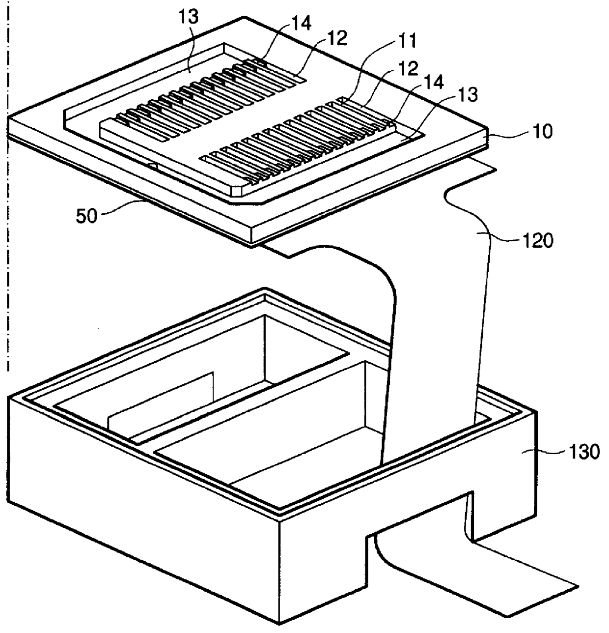
FIG. 1 is a perspective arrangement view of the ink jet type recording head of Embodiment 1 of the present invention. FIGS. 2(a) and 2(b) are cross-sectional views respectively showing different sections of one pressure generating chamber taken in the longitudinal direction, that is, FIG. 2(a) is a cross-sectional view taken on the center line of the piezoelectric vibrator 310 along the line 2A--2A in FIG. 3, and FIG. 2(b) is a cross-sectional view taken at the side end portion of the piezoelectric vibrator 310 along the line 2B--2B in FIG. 3. FIG. 3 is a view showing a positional relation between the cross-sectional views of FIGS. 2(a) and 2(b).

As shown in the drawings, there is provided a passage forming base plate 10, which is composed of a single crystal silicon base plate. One surface of the passage forming base pate 10 is an opening surface, and a piece of elastic film 50 made of silicon oxide is formed on the other surface. On the opening surface of the passage forming base p...

embodiment 2

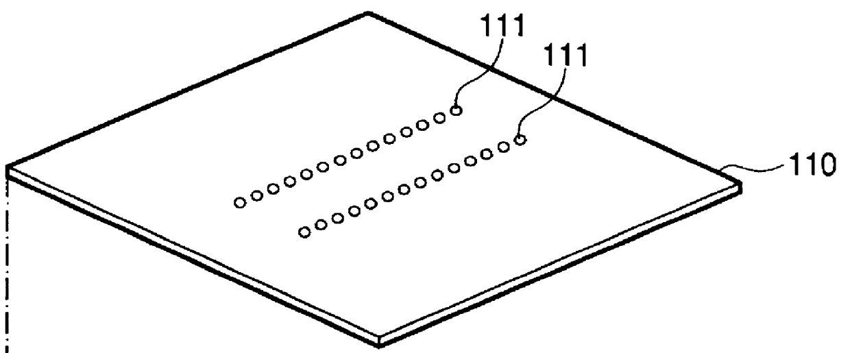
FIGS. 8 to 14 are views showing an ink jet type recording head related to Embodiment 2. The essential structure of this ink jet type recording head is similar to that of the embodiment described before except for one point that a common ink chamber is formed by a different member instead of the reservoir 13 arranged on the passage forming base plate 10. Therefore, like reference characters are used to indicate like parts.

FIG. 8 is an exploded perspective arrangement view of the ink jet type recording head of an embodiment of the present invention. FIG. 9(a) is a plan view, and FIG. 9(b) is a cross-sectional view in the longitudinal direction of one of the pressure generating chambers.

As shown in the drawing, in this embodiment, the passage forming base plate 10 is composed of a single crystal silicon base plate, the face orientation of which is (110). Thickness of the passage forming base plate 10 is usually 150 to 300 .mu.m. It is preferable that the thickness of the passage formin...

embodiment 3

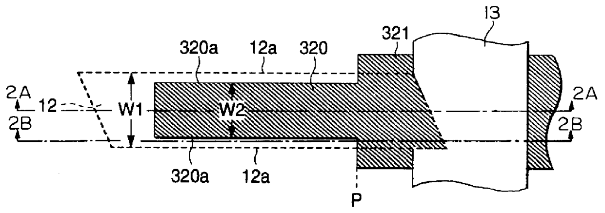
FIG. 20 is a plan view showing a primary portion of the ink jet type recording head of Embodiment 3. The essential structure of the ink jet type recording head of this embodiment is the same as that of Embodiment 2. Therefore, like reference characters are used to indicate like parts.

In this embodiment, the piezoelectric active section 320 is essentially located in a region opposed to the pressure generating chamber 12, and the lower electrode removing section 350 is formed in its periphery. The piezoelectric active section 320 is extended via the narrow width section 323F to a region opposed to the circumferential wall at the end portion in the longitudinal direction of the pressure generating chamber 12. Although the above structure is the same as that of Embodiment 2 described before, there are provided thick film sections 360 on both sides of the narrow width section 323F in the width direction in this embodiment. The thick film sections 360 are regions arranged on both sides of...


PUM


Abstract

An ink jet type recording head is capable of preventing the occurrence of cracks in a portion close to the circumferential wall of the pressure generating chamber of the piezoelectric active section so as to enhance the durability of the recording head. The ink jet type recording head includes a piezoelectric vibrator having a vibrating plate composing a portion of a pressure generating chamber communicated with a nozzle opening, the upper surface of the vibrating plate functioning as a lower electrode, the piezoelectric vibrator also having a piezoelectric active section composed of a piezoelectric layer formed on the surface of the vibrating plate and also composed of an upper electrode formed on the surface of the piezoelectric layer, the piezoelectric active section being formed in a region opposed to the pressure generating chamber, wherein the vibration regulating section is composed of a wide width section in which the piezoelectric layer is wider than the primary portion of the piezoelectric active section, and the wide width section is extended to a side wall and arranged on one end side of the pressure generating chamber in the longitudinal direction.

Description

1. Field of the InventionThe present invention relates to an ink jet type recording head in which a portion of the pressure chamber communicating with the nozzle opening from which ink drops are jetted is composed of a vibrating plate, and a piezoelectric layer is formed on this vibrating plate and ink drops are jetted by the displacement of this piezoelectric layer.2. Description of the Prior ArtThere is provided an ink jet type recording head in which a portion of the pressure chamber communicating with the nozzle opening from which ink drops are jetted is composed of a vibrating plate, and this vibrating plate is deformed by the piezoelectric vibrator so that ink can be pressurized and ink drops are jetted from the nozzle opening. Concerning the ink jet type recording head described above, the following two types of ink jet recording heads are put into practical use. One is an ink jet type recording head in which a piezoelectric vibrator of the longitudinal vibration mode is used...

Claims


Application Information

Patent Timeline
Patent Type & Authority Patents(United States)
IPC IPC(8): B41J2/14B41J2/16B41J2/045B41J2/055
CPCB41J2/14233B41J2/161B41J2/1623B41J2/1629B41J2/1631B41J2/1632B41J2002/14387B41J2002/14419B41J2002/14491B41J2202/03B41J2202/11
Inventor MIYATA, YOSHINAOSAKAI, SHINRIHASHIZUME, TSUTOMU
Owner SEIKO EPSON CORP
Why Eureka
Try Eureka