Foam molding equipment

a molding equipment and foam technology, applied in the field of foam molding equipment, can solve the problems of imposing a limitation on production level, troublesome and time-consuming exchange of molding die 700,

Inactive Publication Date: 2000-09-12
AISIN TAKAOKA CO LTD
View PDF16 Cites 4 Cited by
  • Summary
  • Abstract
  • Description
  • Claims
  • Application Information

AI Technical Summary

Problems solved by technology

Especially, when a large-sized foamed (molded) product is produced by molding dies, the molding dies 700 which is upsized and made heavy is required accordingly, as a result, making such exchange of the

Method used


Image

  • Foam molding equipment
  • Foam molding equipment
  • Foam molding equipment

Examples


Embodiment Construction

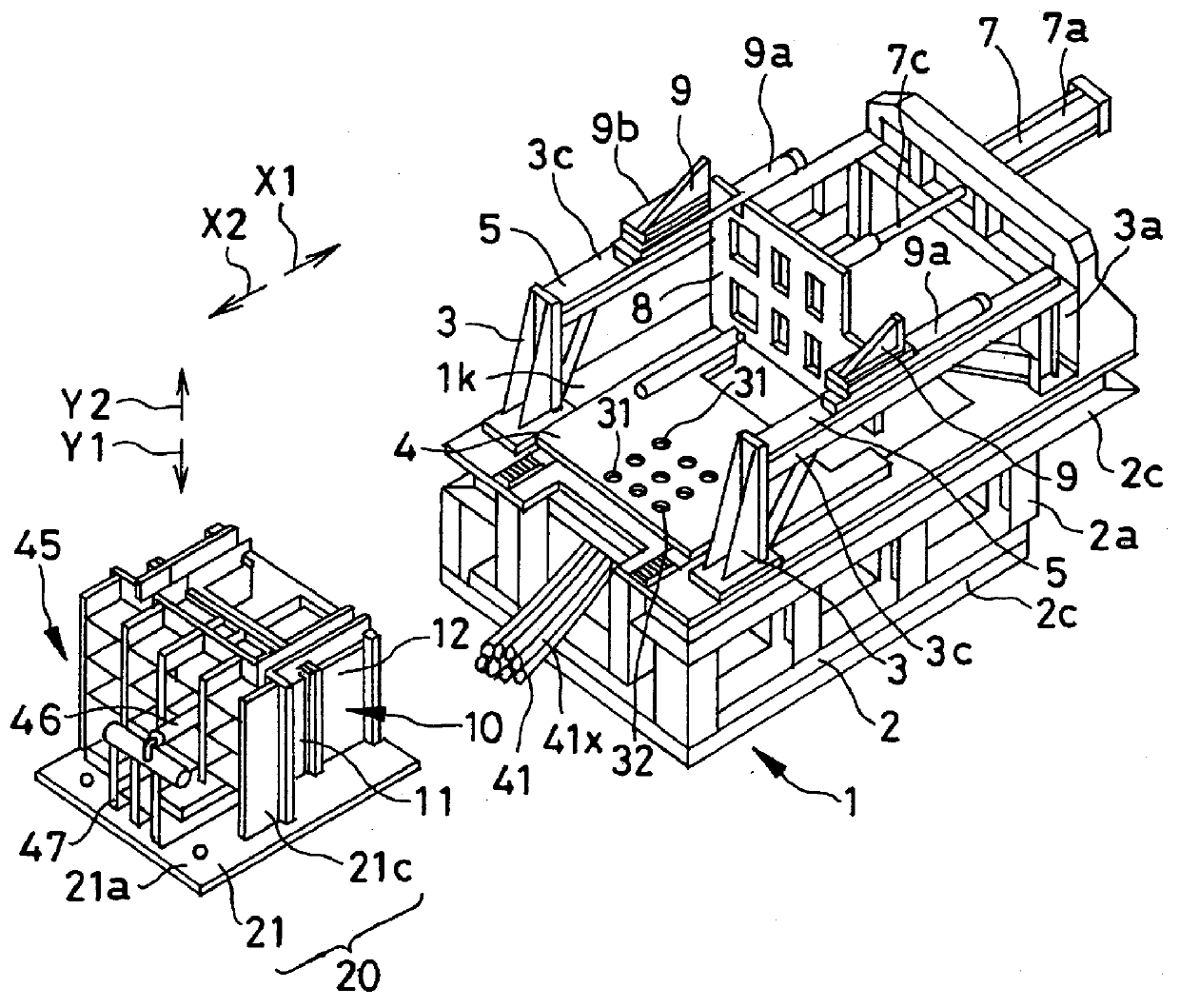
The embodiment of the present invention will be described with reference to FIGS. 1-6. In this embodiment, foam molding equipment is so configured that upsized foamed products can be formed and which can also perform a tie-bar-less operation wherein the use of tie bars is abolished.

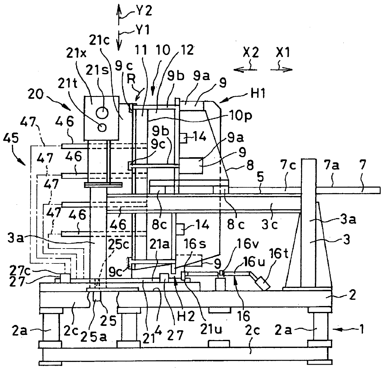
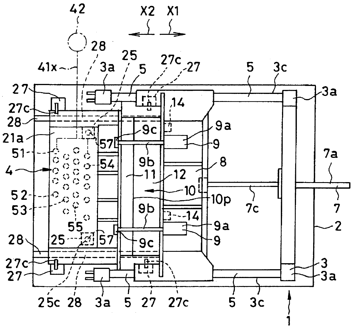
FIG. 1 is a perspective view of a whole equipment. FIG. 2 is a side view of the whole equipment. FIG. 3 is a plan view of the whole equipment. FIG. 6 shows the state of the equipment wherein exchange is in the middle course. FIGS. 1-6 are only conceptual diagrams which are basically common in other diagrams, however, there may be some detailed parts not conforming exactly to those in other diagrams.

As is discernible from FIG. 2, a base frame 1 of a foam molding equipment is provided with a lower frame 2 having longitudinal lower columns 2a and transverse lower columns 2c and with an upper frame 3 having longitudinal higher columns 3a and transverse higher columns 3c. A loading surface 4 with a horizontal ...


PUM


Abstract

The present invention provides foam molding equipment which has an advantage in performing exchange of a molding dies within a short time period and in improving productivity thereof, and which is most suitable, in particular, to the case of using upsized molding dies. The equipment is provided with a fixed die base 21, movable die base 8, a die opening/closing mechanism to move the movable die base 8 together with a movable die 12, and a base frame 1. The fixed die base 21 is detachable from the base frame 1. Molding dies comprising a stationary die 11 and a movable die 12 is preliminarily attached to the fixed die base 21 to form a unit 20. The base frame 1 is provided with a loading surface 4 to load the unit 20 and a unit connector 27 to fix the unit loaded on the loading surface 4 to the base frame 1. The unit 20 is loaded on the loading surface 4 in a detachable manner.

Description

The present invention relates to a molding equipment, particularly, a foam molding equipment which can produce foamed goods by heating and foaming thermoplastic beads (hereinafter referred to as "resin particles") in a molding cavity of molding dies, more particularly, to equipment which has an advantage in shortening time required for exchange of a large-sized die.Conventional equipment which produces a foamed product by heating and foaming resin particles in a molding cavity of a molding dies has been known (as disclosed in JP Patent Kokoku JP-B-55-17695[1980] and JP-B-55-8344[1980]).Such known conventional foam molding equipment is shown in FIG. 7, which is provided with a fixed plate 100, fixed die base 200, a plurality of die bars 300 disposed between the fixed plate 100 and the fixed die base 200, movable die bar base 400 which can be moved along the die bars 300, die opening / closing mechanism 500 supported by the fixed plate 100, and a base frame 600 which serves to support t...

Claims


Application Information

Patent Timeline
IPC IPC(8): B29C31/00B29C33/30B29C44/34B29C44/58B29C67/20B29C44/00B29K105/04
CPCB29C31/006B29C33/305B29C44/58
Inventor YAMADA, YUICHISHIMOMURA, OSAMUYONEZAWA, MASAKIKAMIYA, HIROZIOHSHIMA, KEN
Owner AISIN TAKAOKA CO LTD
Why Eureka
Try Eureka