Scale device

a scale device and scale technology, applied in the field of scale devices, can solve the problems of worsening measurement accuracy, increasing cost, and affecting the accuracy of assembling and maintaining characteristics

Inactive Publication Date: 2000-09-19
DMG MORI CO LTD
View PDF3 Cites 20 Cited by
  • Summary
  • Abstract
  • Description
  • Claims
  • Application Information

AI Technical Summary

Benefits of technology

It is yet another object of the present invention to provide a scale device capable of accommodating position changed without provision of a complex universal mechanism.
In yet another aspect, the present invention provides a scale device including a base unit having a scale carrying recorded graduations secured to a main base member, and a slider unit mounted for sliding relative to the base unit for detecting the graduations recorded on the scale, wherein the scale is formed as a thin plate which has its both ends secured to the main base member, a mid portion of the thin plate being in a floating state, there is provided a detection head unit on the slider unit, the detection head unit has the above-described sensor and there is also provided a sliding member having a groove for maintaining the distance between the sensor and the graduated recording surface of the scale within a range that allows for detection of graduations by the sensor. The detection head unit is adapted for being telescopically moved relative to the scale in a direction along the width of the scale.

Problems solved by technology

However, with the scale device of the structure in which the round-rod-like scale is inserted in the opening in the detection head unit, the telescopic movement of the detection head unit relative to the scale cannot be realized except from the end face side of the scale, thus worsening assembling and maintenance characteristics.
Also, the detection head unit needs to be provided with a complicated universal mechanism in order to cope with position changes to allow for mounting and manufacturing tolerances, thus leading to increased cost.
If, in a scale device employing a thin-plate-like scale, the thin-plate-like scale has a temperature expansion coefficient different from that of the member supporting the thin-plate-like scale, the scale and the supporting member undergo differential deformation thus worsening measurement accuracy.
Moreover, since separate members are used, the problem of increased cost is raised inevitably.

Method used


Image

  • Scale device
  • Scale device
  • Scale device

Examples


Embodiment Construction

Referring to the drawings, preferred embodiments of the present invention will be explained in detail.

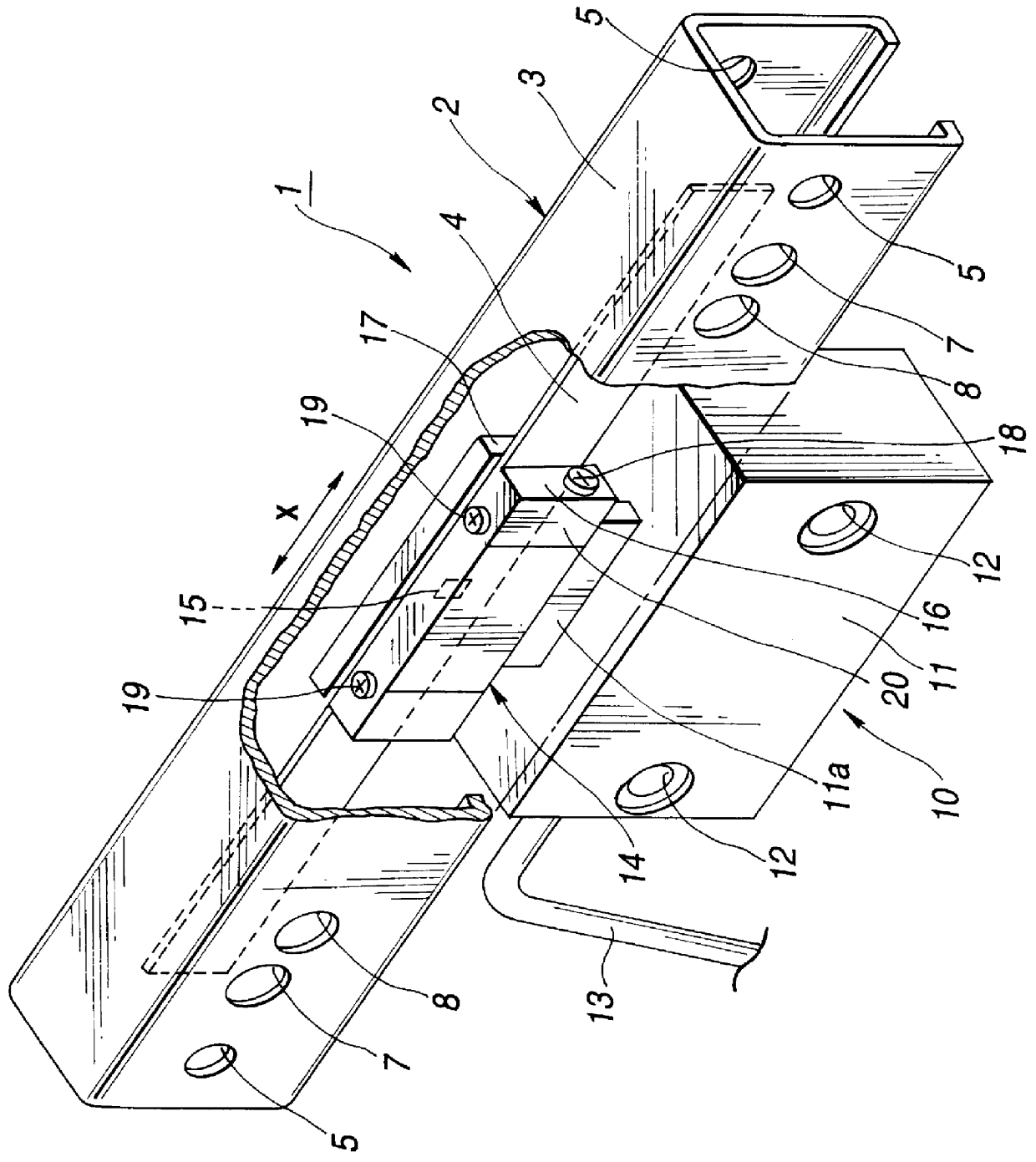
The present invention is applied to a magnetic linear scale device 1 configured as shown in FIGS. 1 to 18.

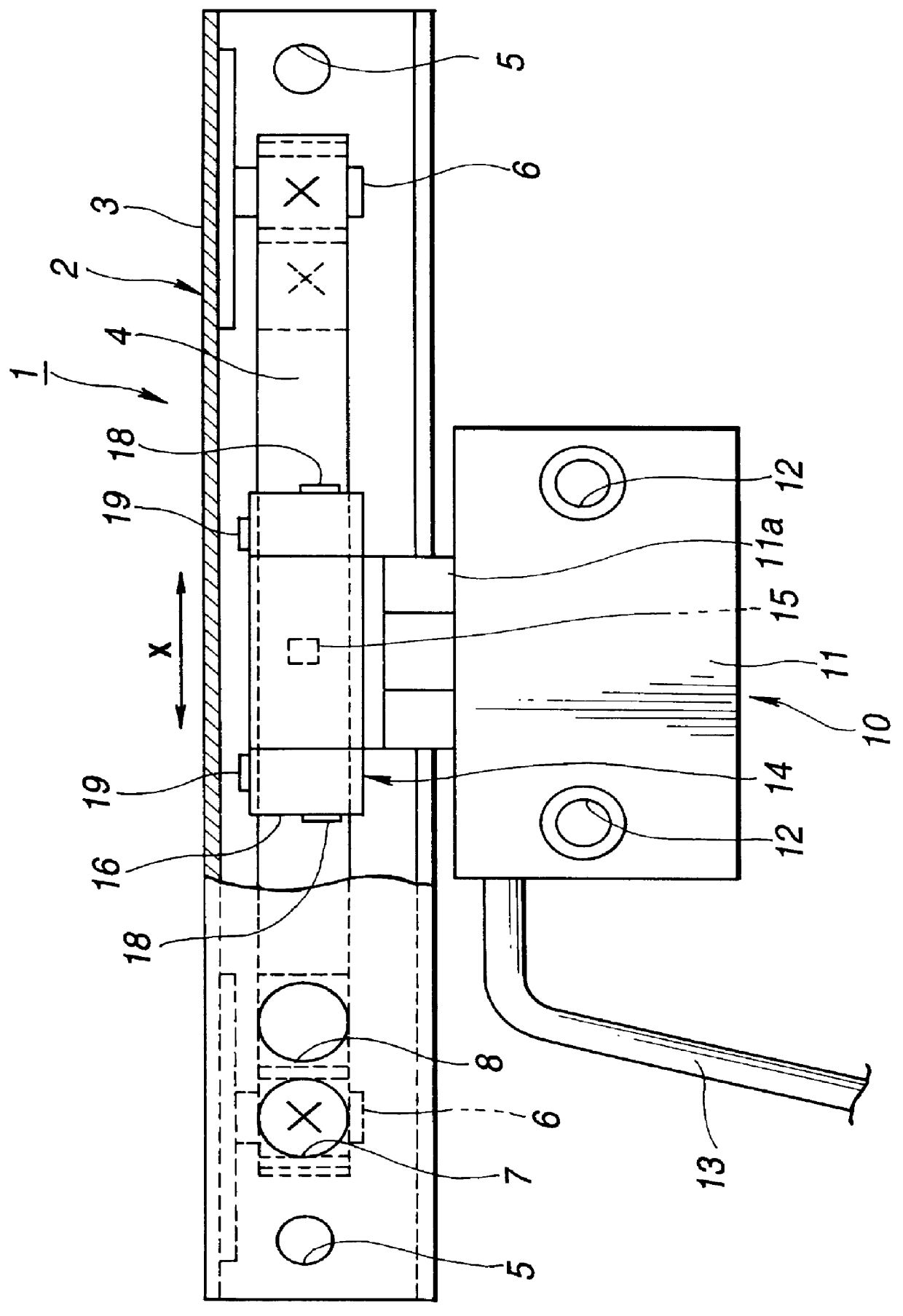
Referring to FIG. 1 showing the magnetic linear scale device 1 with a portion of a casing 3 cut away, the magnetic linear scale device 1 is made up of a base unit 2 and a slider unit 10 mounted for sliding relative to the base unit 2.

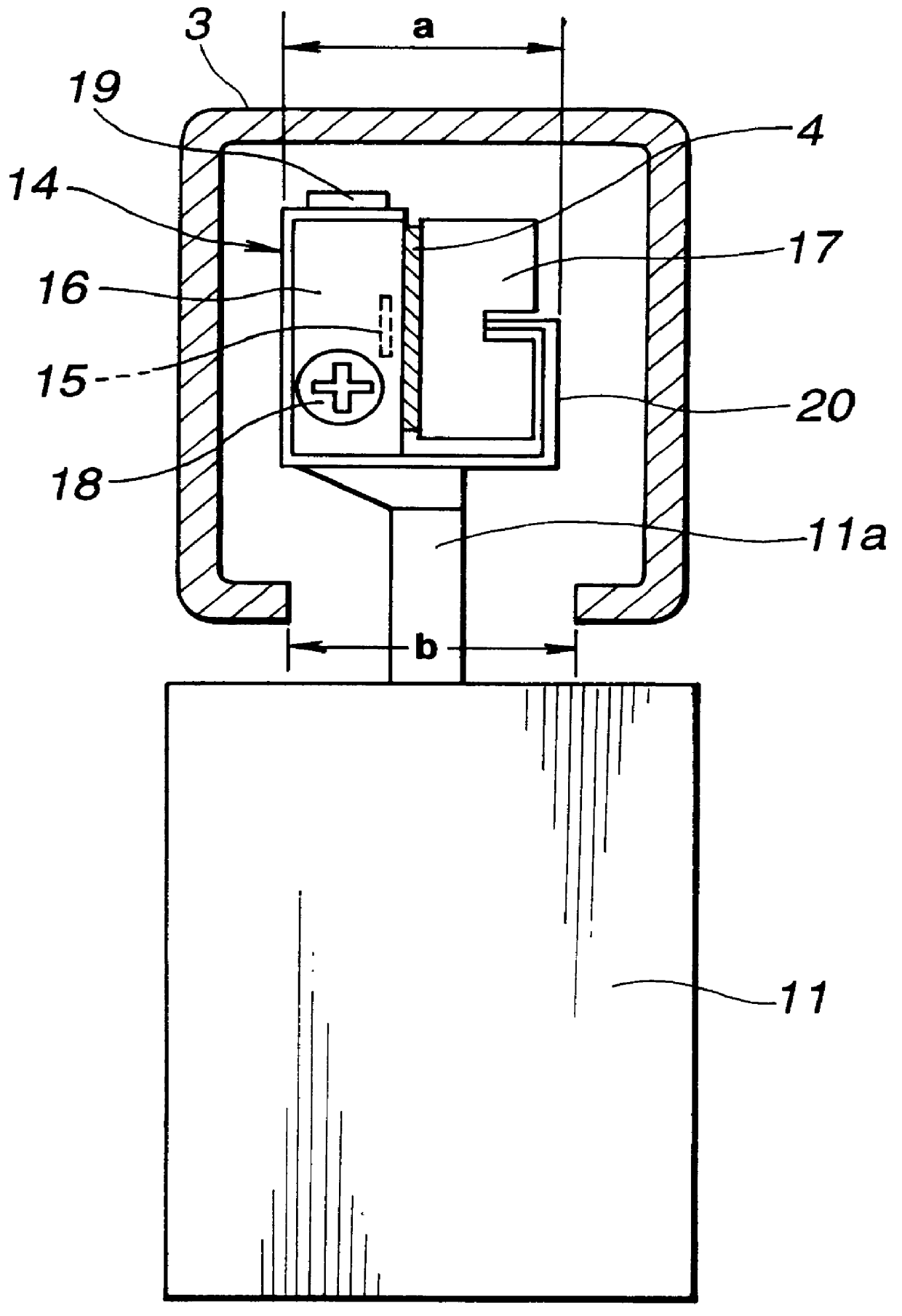
The base unit 2 has an elongated thin-plate-like scale 4 formed of a metallic material in the inside of an elongated casing 3 as a main base portion, as shown in FIG. 2. The base unit 2 is secured by a bolt in a mounting hole 5 formed in the casing 3 to one end of an article under measurement. The slider unit 10 has a sensor 15 for detecting magnetic graduations recorded on the thin-plate-like scale 4 and is secured by bolting in a mounting hole 12 formed in the slider 11 for the movement relative to the article under measurement. The slider unit 10...


PUM


Abstract

A scale device 1 includes a base unit 2 comprised of an elongated casing 3 wherein an elongated thin-plate-like scale 4 is secured with the a mid portion of the thin-plate-like scale 4 kept in a floating state and a slider unit 10 slidable relative to the base unit 2. The slider unit 10 has a sensor 15 for detecting magnetic graduations recorded on the thin-plate-like scale 4. A reference sliding member 16 is provided for maintaining a constant separation between the sensor 15 and the recording surface of the magnetic graduations of the thin-plate-like scale 4. A pressing sliding member 17 is provided for pressing the reference sliding member 16 so that the recording surface of the magnetic graduations are perpetually contacted with the reference sliding member 16. A detection head unit 14 is movable telescopically relative to the thin-plate-like scale 4 in a direction along the width of the scale.

Description

1. Field of the InventionThis invention relates to a scale device used for detecting the position of a straight line in machine tools or in industrial machines by way of relative position detection.2. Related ArtThis type of the scale device is composed in general of a base unit, having a graduated scale secured to a base member, and a slider unit, mounted relatively slidably on this base unit and carrying a sensor adapted for detecting the graduations recorded on the scale.In this type of the conventional scale device, a scale in the shape of a round rod is provided as the scale on the base unit side, and a detection head unit having a sensor for detecting the graduations is provided on the slide unit side. The above-described scale is slidably inserted in an opening in the detection head unit. There is also provided a universal mechanism in the detection head unit to permit mounting tolerances and tolerances for component parts.Among these scale devices, there is such a scale devi...

Claims


Application Information

Patent Timeline
Patent Type & Authority Patents(United States)
IPC IPC(8): G01D11/00G01D11/02
CPCG01D11/02
Inventor OCHIAI, OSAMUONOE, KEN
Owner DMG MORI CO LTD
Why Eureka
Try Eureka