Calibration device for a parallel kinematic manipulator

a kinematic manipulator and calibration device technology, applied in the direction of mechanical measuring arrangements, instruments, force/torque/work measurement apparatus, etc., can solve the problems of inaccurate calibration, lack of practical calibration device for those calibration algorithms, and lack of sufficient accuracy, etc., to achieve high degree of accuracy, high geometric precision, and low manufacturing cost

Inactive Publication Date: 2003-07-01
DR JOHANNES HEIDENHAIN GMBH
View PDF22 Cites 57 Cited by
  • Summary
  • Abstract
  • Description
  • Claims
  • Application Information

AI Technical Summary

Benefits of technology

The device according to the present invention allows the actual TCPs to be determined or measured with a high degree of accuracy. Thus, a suitably designed parallel kinematic manipulator can also ultimately be used to position a machine tool.
The device according to the present invention has the further advantage that it is essentially made up of simp

Problems solved by technology

In general, the actual geometry of such a manipulator is not identical to the designed ideal geometry due to manufacturing and assembly tolerances.
These deviations in turn result in accuracy deviatio

Method used


Image

  • Calibration device for a parallel kinematic manipulator
  • Calibration device for a parallel kinematic manipulator
  • Calibration device for a parallel kinematic manipulator

Examples


Embodiment Construction

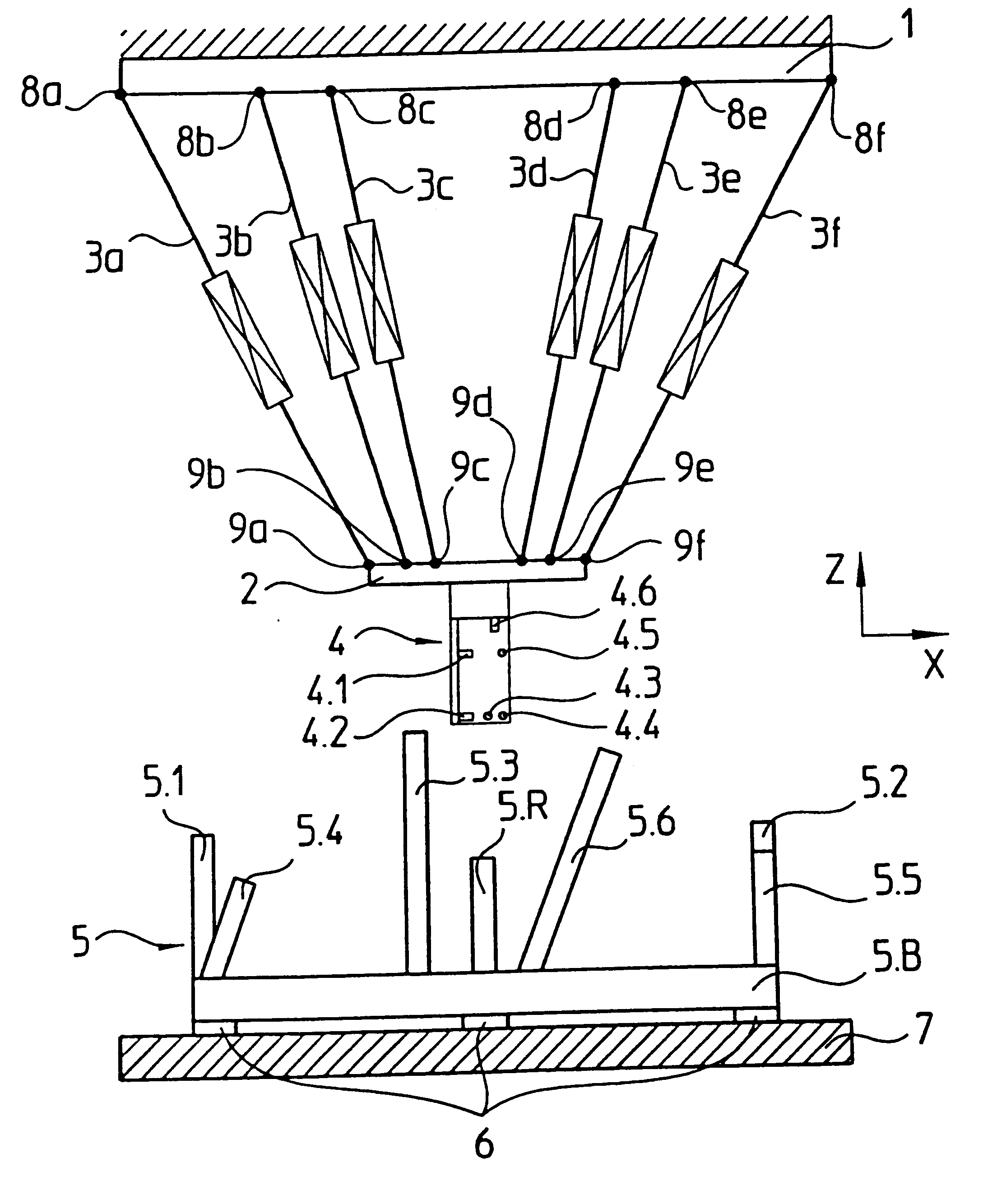
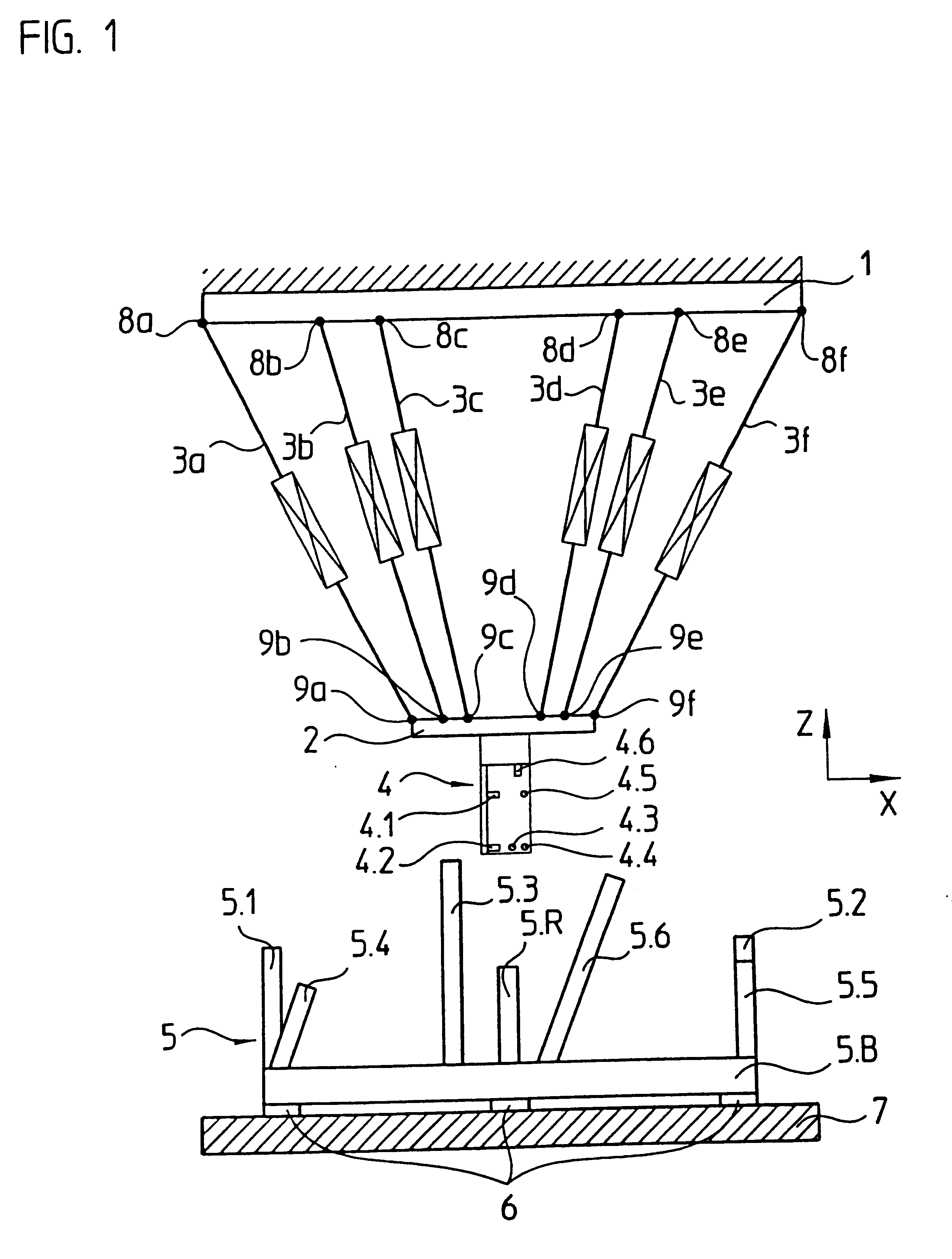
One embodiment of the calibration device according to the present invention, used in conjunction with a typical parallel kinematic manipulator, is schematically illustrated in FIG. 1.

In this embodiment, the parallel kinematic manipulator includes a base unit 1 and a manipulator platform 2 connected thereto via six variable length telescopic arms and actuators 3a-3f. Six joints 8a-8f, and 9a-9f are provided respectively between actuators 3a-3f and manipulator platform 2, and between actuators 3a-3f and base unit 1. Thus the manipulator geometry illustrated in FIG. 1 includes a total of twelve separate joints 8a-8f, 9a-9f.

Manipulator arm 2 furthermore has a workholding fixture (not shown in this figure), which for example, may be used to hold a tool, when the manipulator is used as a machine tool. The manipulator geometry shown can also be used in other manners, for example as a coordinate measuring device. In that case, the workholding fixture on manipulator platform 2 would be used ...


PUM


Abstract

A calibration device for a parallel kinematic manipulator having a base unit and a manipulator platform movable with respect thereto, the manipulator platform being connected to the base unit via a plurality of joints and a plurality of variable length actuators. The calibration device for measuring n deviations in order to determine m unknowns includes a test workpiece that is mountable in a definite spatial position with respect to the base unit and has I=m/n measuring mandrels. The calibration device also has a probing unit attached to the manipulator platform, and including n probing subsystems, the probing subsystems each including a distance measuring device for measuring the spatial position and spatial orientation of the measuring mandrels on the test workpiece.

Description

The present invention relates to a device for calibrating a parallel kinematic manipulator, and more specifically to a device suitable for calibrating a machine tool designed according to the hexapod principle.DESCRIPTION OF RELATED ARTAlternative machine tool kinematics are being increasingly used in designing machine tools, such as in machine tools designed according to the hexapod principle or as Stewart platforms. In such machine tools, or more generally in parallel kinematic manipulators, the relative motion between workpiece and tool is effected by the simultaneous motion of actuators normally moving in six translational and / or rotational axes. The respective actuators normally consist of variable-length telescopic arms.In order to ensure the required positional accuracy, the geometry of the parallel kinematic manipulator being used must be known with extreme precision. In general, the actual geometry of such a manipulator is not identical to the designed ideal geometry due to...

Claims


Application Information

Patent Timeline
IPC IPC(8): B23Q1/25B23Q1/54B25J9/16G01B21/02G01B21/04G01B3/30
CPCB23Q1/5462B25J9/1623B25J9/1692G01B3/30G01B21/042
Inventor SCHRODER, WILHELMBRAASCH, JAN
Owner DR JOHANNES HEIDENHAIN GMBH
Why Eureka
Try Eureka