Magnetic bearing

a bearing and magnetic technology, applied in the field of magnetic bearings, can solve the problems of large current loss, inability to directly apply construction, and heat generation in the rotation sha

Inactive Publication Date: 2000-09-19
NSK LTD
View PDF20 Cites 79 Cited by
  • Summary
  • Abstract
  • Description
  • Claims
  • Application Information

AI Technical Summary

Problems solved by technology

Namely, the polarity of the electromagnetic poles of the radial magnetic bearing is alternating in the rotational direction, and therefore there is a possibility that a large hysteresis loss and a large eddy current loss develop in each laminate of disk-shaped sheets mo

Method used


Image

  • Magnetic bearing
  • Magnetic bearing
  • Magnetic bearing

Examples


first embodiment

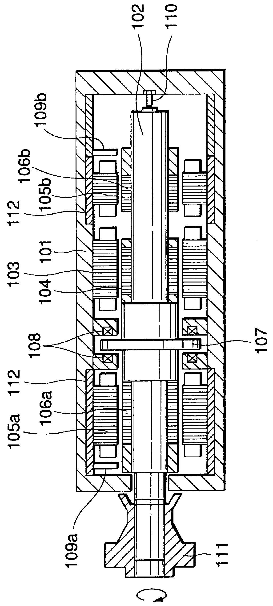
A first embodiment of the present invention will now be described with reference to the drawings. FIG. 4 is a longitudinal cross-sectional view of the first embodiment of a magnetic bearing of the present invention, taken through an axis thereof. FIG. 5 is a cross-sectional view taken along the line V--V of FIG. 4. FIG. 6 is a perspective view of the radial magnetic bearing (corresponding to FIG. 5) of this embodiment, showing a cross-section of coils wound on stator magnetic poles.

A rotation shaft 1 is rotatably supported within a housing 100 in a manner described later. A radially-extending flange portion 80 is formed on a generally central portion of the rotation shaft 1. Rotor cores 2 are fitted respectively on those portions of an outer peripheral surface of the rotation shaft 1 disposed adjacent respectively to axial opposite ends thereof. The rotor core 2 comprises a laminate of I-shaped magnetic steel sheets stacked together in a circumferential direction.

A retaining member ...

second embodiment

FIG. 9 is a longitudinal cross-sectional view of a second embodiment of a magnetic bearing of the present invention, taken through an axis thereof. FIG. 10 is a plan view of the magnetic bearing, with an outer tube removed. FIG. 14 is a cross-sectional view taken along the line XIII--XIII of FIG. 9. FIGS. 11 and 12 are views explanatory of the construction of a radial stator and the construction of a radial housing, respectively.

The magnetic bearing of the second embodiment is a modified form of the magnetic bearing of the first embodiment, and corresponding portions will be designated by identical reference numerals, respectively.

As shown in FIGS. 9 and 10, a rotation shaft 1 is rotatably supported by the magnetic bearing covered with the outer tube 100b, and is disposed coaxially with this magnetic bearing. As in the first embodiment, a flange portion 80 and rotor cores 2 are formed on the rotation shaft 1.

As described above, the rotor core 2 comprises a laminate of I-shaped magne...


PUM


Abstract

There is disclosed a magnetic bearing which is an improvement over conventional radial magnetic bearings, and has a very small bearing loss. At least three U-shaped laminates 10 of electromagnetic steel sheets are circumferentially arranged around a rotation shaft 1, and are fixedly mounted on a housing 100. Exciting coils 31 and 32 are wound on each electromagnetic steel sheet laminate 10, and permanent magnets 20 and 21 are provided in the laminate 10. Rotor cores 2, each comprising a laminate of I-shaped electromagnetic steel sheets stacked together in the circumferential direction, are mounted on the rotation shaft 1 in such a manner that each rotor core 2 is opposed to magnetic pole surfaces of the electromagnetic steel sheet laminates 10. In accordance with a signal from position sensors 5 which detect the radial position of the rotation shaft 1, control current is caused to flow through the exciting coils 31 and 32 to thereby control the position of the rotation shaft 1. Thus, merely by causing the control current to flow through the exciting coils 31 and 32 when this is required, the control of the rotation shaft 1 can be achieved, and with this method, the energy consumption can be much reduced.

Description

1. Field of the InventionThis invention relates to a magnetic bearing which rotatably supports a rotating member, utilizing a magnetic attraction force.2. Related ArtThere is known a magnetic bearing which rotatably supports a rotating member, utilizing a magnetic attraction force. Such a magnetic bearing can support the rotating member in a non-contact condition, and therefore has many advantages such as a small bearing loss, a maintenance-free design, low noises, the obviation of the need for a lubricating oil, and the capability of being used in a vacuum condition.A conventional magnetic bearing will be described with reference to the drawings. FIG. 1 is a cross-sectional view of a magnetic bearing disclosed in Japanese Patent Unexamined Publication No. 4-171316. In this Figure, the magnetic bearing broadly comprises two members, that is, a shell 101 and a rotation shaft 102. A motor stator 103 is mounted on an inner peripheral surface of the shell 101, and a motor rotor 104 is m...

Claims


Application Information

Patent Timeline
IPC IPC(8): F16C39/06F16C39/00F16C32/04
CPCF16C32/0459F16C32/0465F16C32/0489F16C2380/26
Inventor FUKUYAMA, HIROMASATAKIZAWA, TAKESHI
Owner NSK LTD
Why Eureka
Try Eureka