Torque support

a technology of torque support and ring, which is applied in the direction of mechanical equipment, transportation and packaging, and machining details, can solve the problems of correspondingly elaborate external toothings, and achieve the effect of simple and economical manufacture and certain elasticity

Inactive Publication Date: 2000-09-26
KONECRANES GLOBAL
View PDF15 Cites 19 Cited by
  • Summary
  • Abstract
  • Description
  • Claims
  • Application Information

AI Technical Summary

Benefits of technology

It is the object of the invention to provide a torque support which is simple and economical to manufacture, mechanically stable, has a certain elasticity and is adaptable to virtually any gear unit connection surface shapes.
In terms of manufacturing technique, the torque support can be manufactured in a very simple manner when the bushings are embedded with a minus tolerance relative to the contact face at the screw head side. The minus tolerance ensures that the bushings will at most terminate flush with the contact face on the screw head side. Because of the manufacturing tolerances, a flawless frictional engagement without additional expenditure is always guaranteed.
For uniform contact of the torque support against the second housing, it is advantageous when the contacting surface is an annular surface.

Problems solved by technology

However, it is disadvantageous that a ring with a correspondingly elaborate external toothing must be provided at the gear unit housing.

Method used


Image

  • Torque support
  • Torque support
  • Torque support

Examples


Embodiment Construction

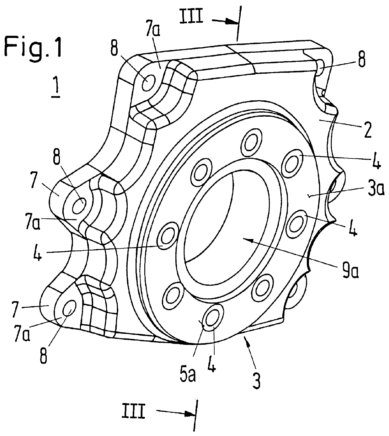
FIG. 1 shows a perspective view of a torque support 1 according to an embodiment of the present invention mountable for supporting occurring torques between a first housing of a driven unit such, for example, as a wheel block housing and a second housing of a driving unit such, for example, as a gear unit housing. The torque support 1 has a scalloped plastic base body 2. A first planar contact face 3 including an annular surface 3a is formed on the front side of the plastic base body 2. Hollow-cylindrical bushings 4 oriented with their longitudinal axis perpendicular to the annular surface 3a are circumferentially arranged in the planar annular surface 3a at equal angular distances from one another about a center of the annular surface 3a. Each of the bushings 4 has a front axial end face 5a and a rear axial end face 5b (see FIG. 3). The bushings are arranged in the plastic body 2 such that front axial end face 5a of the bushings 4 terminates, at maximum, flush with the annular surf...


PUM

PropertyMeasurementUnit
torqueaaaaaaaaaa
areaaaaaaaaaaa
constant angular distancesaaaaaaaaaa

Abstract

A torque support mountable between a first housing of a driven unit and a second housing of a driving unit includes a scalloped one-piece plastic base body having a first side connectable with the first housing and a second side connectable with the second housing so as to be fixed with respect to rotation relative to both the first housing an the second housing. The first side includes a first planar contact face with through-openings for fastening with the first housing and the second side includes a flange-like edge area with a second planar contact face for resting against the second housing. The plastic piece is injection molded with support webs and includes metal bushings which are arranged perpendicular to the second planar contact face to provide a torque support which is simple and economical to manufacture, mechanically stable, has a certain elasticity and is adaptable to virtually any gear unit connection surfaces. The bushings may be pressed toward the second housing with fastening means while the second planar contact face presses against the second housing in a frictional engagement. Through-openings are formed at the flange-like edge area of the plastic base body for connection of the torque support to the first housing.

Description

1. Field of the InventionThe invention is directed to a torque support connectable between a first housing of a drive unit and a second housing of a driven unit.2. Description of the Related ArtGerman reference DE 40 21 054 C2 discloses a prior art torque support made from plastic which is arranged between the housing of a wheel block and the housing of a gear unit. One side of the torque support is connected to the wheel block housing and the other side is connected to the gear unit housing such that the torque support is fixed with respect to rotation relative to both the wheel block housing and the gear unit housing. The torque support has a flange with bore holes for the connection to the wheel block housing. The flange may be fastened to an appropriate surface at the wheel block housing by fastening elements such as screws. The connection of the torque support to the gear unit is effected by an outer ring formed at the torque support with an internal toothing. An inner ring arr...

Claims


Application Information

Patent Timeline
Patent Type & Authority Patents(United States)
IPC IPC(8): F16H57/02B60B35/16F16H57/025
CPCF16H57/025Y10T74/2186
Inventor GIEVERS, WINFRIEDGLOGOWSKI, JENSSCHMIDT, HEINZWOYK, RAINER
Owner KONECRANES GLOBAL
Why Eureka
Try Eureka