Zoom lens having an image stabilizing function

a technology of zoom lens and image stabilization function, which is applied in the field of zoom lens, can solve the problems of difficult problem of improving the compact form of the entire lens system, and elongation of the physical length of the complete lens

Inactive Publication Date: 2000-09-26
CANON KK
View PDF13 Cites 50 Cited by
  • Summary
  • Abstract
  • Description
  • Claims
  • Application Information

AI Technical Summary

Benefits of technology

Another object of the invention is to provide a zoom lens having an image stabilizing function and good optical performance. To this end, the zoom lens of the character described above is used as the base. In application to this zoom lens, the method of correcting shaking of the image is by moving part of the zoom lens, or the shiftable lens unit in directions perpendicular to an optical axis. To this purpose, as the shiftable lens unit, a one of small size and light weight is selected to use. In addition, its small decentering movement is reflected to correct large amplitude of shaking of the image. Furthermore, as the shiftable lens unit moves to parallel decenter, any of the decentering aberrations described before is produced to a smaller amount than was heretofore common.

Problems solved by technology

In the former case, however, to maintain good stability of aberration correction throughout the zooming range, it becomes necessary to increase the number of constituent lenses, giving rise to a difficult problem of improving the compact form of the entire lens system.
This leads to elongation of the physical length of the complete lens.
Particularly in a case where the lens units move in complicated relation, the mounting mechanism for the movable lens units becomes very elaborate, giving rise to a difficult problem of improving the compact form of the entire lens system.
For this reason, if the paraxial zone alone is taken into consideration in controlling the decentering of the shiftable lens unit to correct the shaking of the image, it is in the marginal zone that a similar phenomenon to the shaking of the image takes place, causing the optical performance to lower objectionably.
According to the prior art, however, the image stabilizing optical systems of the type using an optical member as arranged, regardless of vibrations, to be held in fixed spatial alignment with the line of sight, are not suited to be used in instruments of small size and light weight, because this optical member is difficult to operatively support and because such optical systems are difficult to realize in compact form.
Another type of image stabilizing optical system using a variable angular prism as arranged in the frontmost position, though having a merit that, when correcting the shaking, all decentering aberrations except chromatic ones are produced to almost nothing, has problems that the driving members become large in size and that the decentering chromatic aberrations produced from the prism are difficult to correct with ease.
However, there is a difficult problem of simultaneously fulfilling the requirements of correcting well all of the aberrations produced by decentering, namely, decentering coma, decentering astigmatism and decentering curvature of field and of realizing reflection of the sufficiently small amount of decentering movement to a sufficiently great effect of stabilizing the image.
At this time, particularly in the wide-angle end, the symmetry of the refractive power arrangement is worsened.
So, it becomes difficult to correct coma and other asymmetric aberrations.
Conversely when the upper limit of the condition (1) is exceeded, as this means that the absolute value of the focal length of the fourth lens unit is too large as compared with the longest focal length of the entire system, it becomes difficult to correct the variation of spherical aberration with zooming, since this correction is done mainly by the fourth lens unit.
When the lower limit of the condition (2) is exceeded, as this means that the absolute value of the second lens unit is too small, it becomes difficult mainly in the telephoto end to correct coma and astigmatism.
So, the physical length of the complete lens increases objectionably.
When the absolute value of the focal length of the sixth lens unit is too large as exceeding the upper limit, it is in the general case that the total length of the complete lens increases objectionably.
However, virtually, the above-described factors are related to one another complicatedly.

Method used


Image

  • Zoom lens having an image stabilizing function
  • Zoom lens having an image stabilizing function
  • Zoom lens having an image stabilizing function

Examples


numerical example 2

Numerical Example 3:

TABLE 1

According to the invention, as described above, the zoom lens is constructed with six lens units of specified refractive powers in total, wherein proper rules are set forth for the refractive powers of the lens units and for the relation in which the lens units move when zooming, so that the number of constituent lenses is reduced to a minimum to insure that a shortening of the total length of the entire lens system is achieved, while still permitting high optical performance to be maintained throughout the entire zooming range. Thus, a zoom lens of the telephoto type having a range of about 4 is achieved.

Another embodiment in which further improvements are made is described below.

numerical examples 4 to 7

of zoom lenses of the invention are shown in FIGS. 7(A), 7(B) and 7(B) through FIGS. 10(A), 10(B) and 10(C). The aberrations of the zoom lenses of the numerical examples 4 to 7 are shown in FIGS. 11(A)(1)-11(A)(4), 11(B)(1)-11(B)(4), and 11(C) (1)-11(C)(4) through FIGS. 14(A)(1)-14(A)(4), 14(B)(1)-14(B)(4), and 14(C)(1)-14(C)(4) with suffix (A) in the wide-angle end, suffix (B) in a middle position and suffix (C) in the telephoto end.

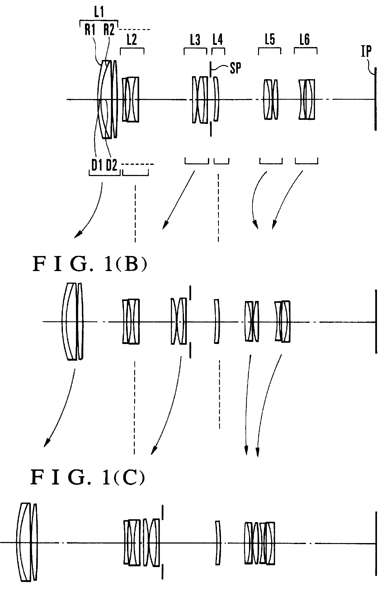
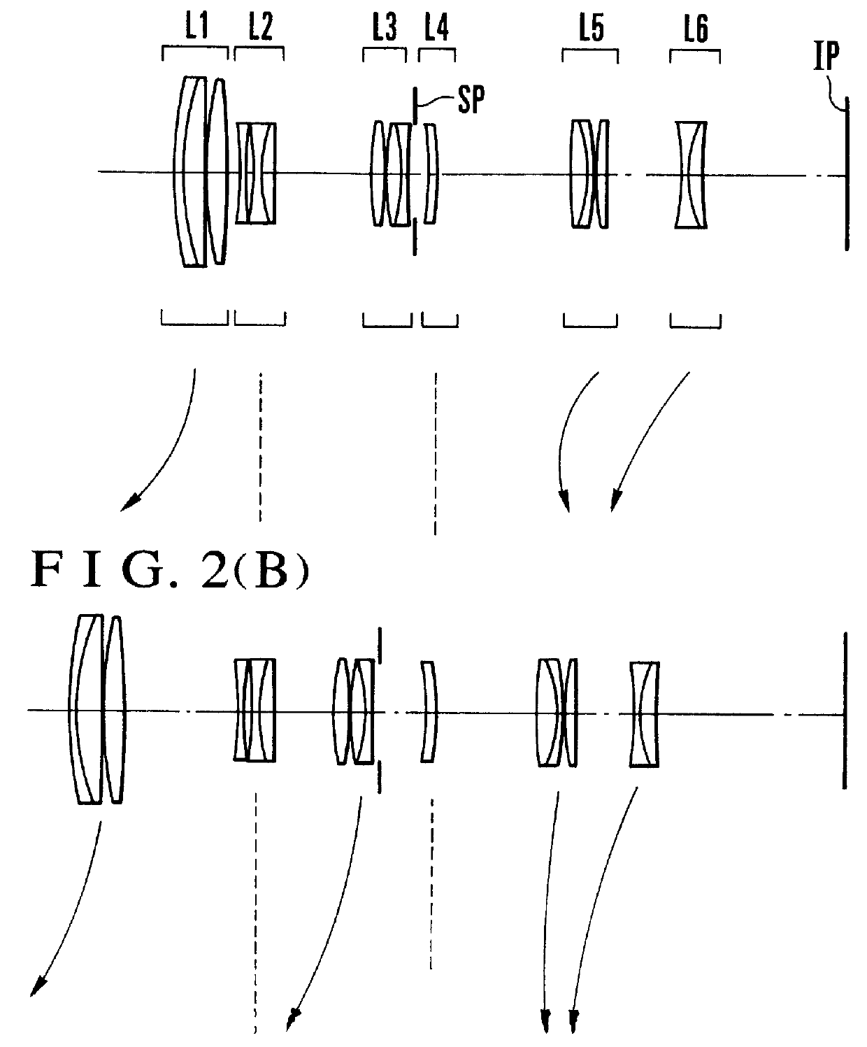
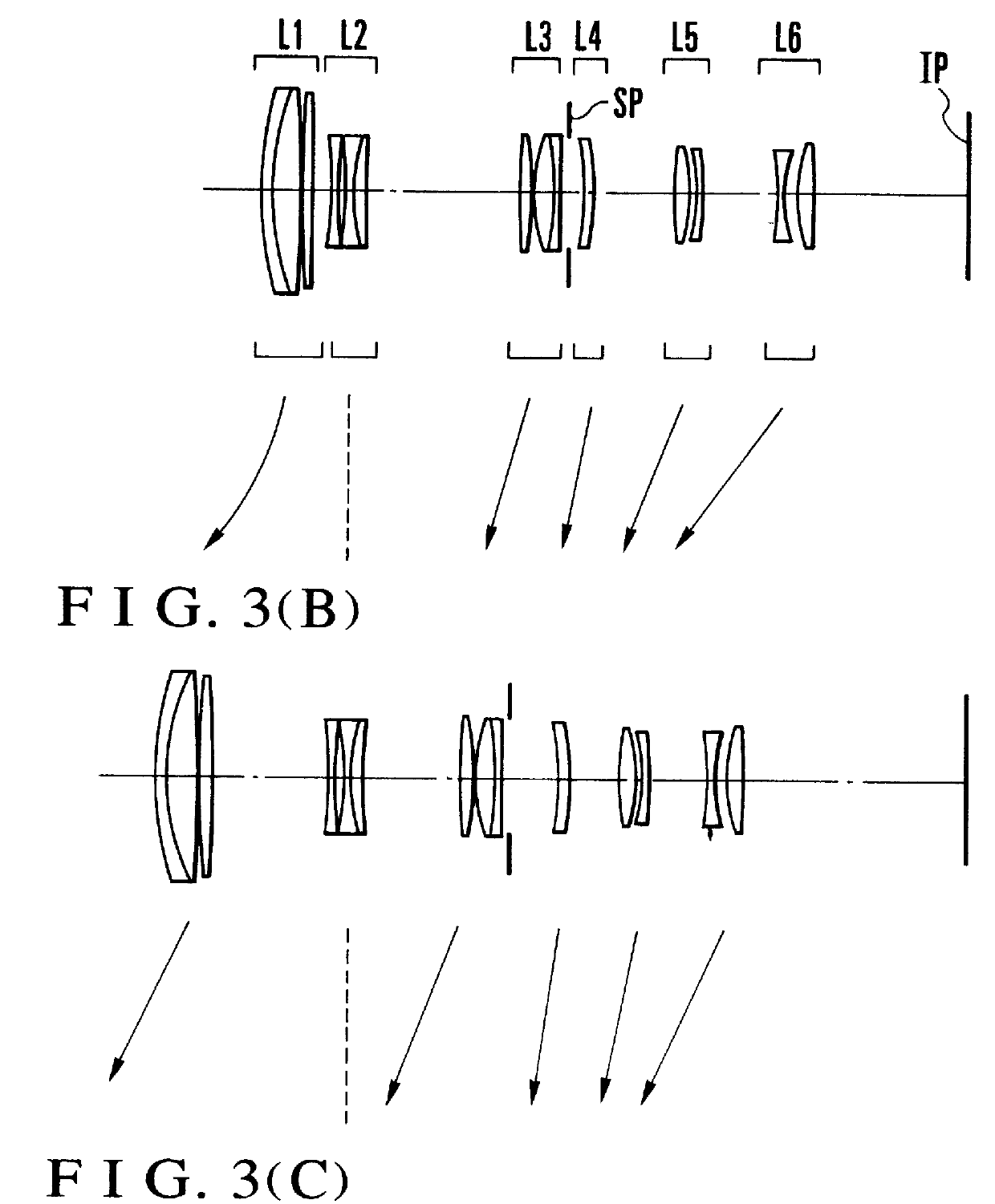
The zoom lens comprises, from front to rear, a first lens unit L1 of positive refractive power, a second lens unit L2 of negative refractive power, a third lens unit L3 of positive refractive power, a fourth lens unit L4 of negative refractive power, a fifth lens unit L5 of positive refractive power and a sixth lens unit L6 of negative refractive power. SP stands for a stop. The arrows indicate the loci of motion of the lens units when zooming from the wide-angle end to the telephoto end.

One of the characteristic features of the present embodiment is th...

numerical example 4

ln Z.sub.2 / ln Z=0.8975; f1 / .sqroot.fW.multidot.fT=0.8742


PUM


Abstract

A zoom lens is disclosed comprising, from front to rear, a first lens unit of positive refractive power, a second lens unit of negative refractive power, a third lens unit of positive refractive power, a fourth lens unit of negative refractive power, a fifth lens unit of positive refractive power and a sixth lens unit of negative refractive power, wherein, during zooming from the wide-angle end to the telephoto end, the air separations between the i-th and (i+1)st lens units are made to vary properly and the ratio of the focal length of the fourth lens unit to the longest focal length of the entire system is made to have a proper value. In particular, a zoom lens is disclosed wherein the second lens unit is made to decenter to stabilize the image.

Description

1. Field of the InventionThis invention relates to zoom lenses of the telephoto type suited to 35 mm cameras, video cameras or electronic still cameras and, more particularly, to zoom lenses having four to six lens units in total, of which certain ones are movable for zooming, and having as high a range as 4 or thereabout with maintenance of a high optical performance throughout the zooming range, while still permitting improvements of the compact form of the entire system.2. Description of the Related ArtFor photographic cameras and video cameras, there have been demanded zoom lenses of high range with high optical performance. Of these, the telephoto type has been proposed in a wide variety of multi-unit zoom lenses in which three or more lens units are movable for zooming.For example, a 3-unit zoom lens of plus-minus-plus power arrangement in this order from the object side, a 4-unit zoom lens of plus-minus-plus-plus power arrangement, another 4-unit zoom lens of plus-minus-minus...

Claims


Application Information

Patent Timeline
Patent Type & Authority Patents(United States)
IPC IPC(8): G02B15/163G02B15/173
CPCG02B15/173G02B15/1461G02B15/145113
Inventor HAYAKAWA, SHINGOMOMOKI, KAZUHIKO
Owner CANON KK
Why Eureka
Try Eureka