
Joist hanger and installation method

a technology of poured concrete and hangers, which is applied in the direction of building reinforcements, constructions, buildings, etc., can solve the problems of reducing the load-bearing capacity of embedded joists, and affecting the use of finished walls. , to achieve the effect of reducing or eliminating the presence of deleterious voids in finished walls

Inactive Publication Date: 2000-10-17
WISE MICHAEL A
View PDF15 Cites 47 Cited by
  • Summary
  • Abstract
  • Description
  • Claims
  • Application Information

AI Technical Summary

Benefits of technology

It is also an object of the invention to provide a joist hanger for a poured concrete wall, and an installation method therefor, featuring ease of use.
Another object of the invention is to provide a joist hanger for a poured concrete wall, and an installation method therefor, which reduces or eliminates the presence of deleterious voids in the finished wall.
In a preferred embodiment, each anchor member which extends rearwardly from the base to a depth exceeding the nominal thickness of the panel proximate to the through-hole, and the deflecting surface is conveniently defined by a flanged end portion of each anchor member. Also in the preferred embodiment, each anchor member is nonremovably secured to the base, thereby ensuring both that the anchor member extends to the proper depth and that the deflecting surface is properly oriented to vertical when the base is positioned against the panel's front face. The base may preferably include an aperture for receiving an end of the anchor member in order to increase the load-carrying capacity of the joist hanger.
The joist hanger further includes a plurality of apertures formed in the periphery of the base along the two opposite edges thereof which, upon installation of the joist hanger, form the joist hanger's vertical edges. The apertures are adapted to receive fasteners with which to secure the base to the panel's front face prior to pouring the material against the panel's rear face. The joist hanger base also preferably includes a vent extending from the back side of the base to its front side. Preferably, the vent is positioned near an anchor member such that, when the base is positioned against and secured to the front face of the panel, the vent overlies a through-hole into which the anchor member extends while further being positioned in a vertical plane above each and every anchor members extending into that hole. Thus positioned, the vent facilitates monitoring the proper flow of poured material into the panel's through-hole.
In accordance with yet another feature of the invention, where the base of the joist hanger includes a vent extending from the back side of the base to its front side, the method preferably includes monitoring the vent for the presence of material during the pouring step. In this manner, the complete filling of the through-hole with poured material and, hence, the absence of deleterious voids in the poured material, may be conveniently confirmed.

Problems solved by technology

Unfortunately, this first method for supporting joists requires the concurrent and precisely-coordinated efforts of tradesmen skilled in both concrete and carpentry, with an attendant increase in labor costs.
A failure to properly position the projecting joist end relative to the preform can substantially effect either the quality of the support provided by the wall or the integrity of the wall, or both.
Building codes often prohibit direct contact between concrete and wood and, further, provide that joists imbedded within concrete be "fire cut" with a vertical chamfer such that the joist's upper edge does not catch the wall, thereby reducing the load-bearing capacity of such embedded joists.
And, of course, the vertical repositioning of any given joist is virtually impossible.
Perhaps most significantly, this first method often results in the creation of air pockets or "voids" in the poured concrete wall directly beneath each projecting joist end.
Such voids can significantly contribute to premature failure of the juncture of wall and joist.
While the second method is readily practiced by concrete tradesmen alone, the bight portion of the U-shaped bracket renders the second method particularly susceptible to void formation beneath each bracket.
As a result, in the finished wall, each joist is undesirably supported by the bracket in an extended cantilevered fashion, with the end of the joist spaced from the poured concrete a distance equal to the thickness of the interior panel.
While its rearwardly-tapering holes facilitate the flow of poured concrete around each anchor bolt and, hence, reduce the occurrence of deleterious voids in the finished wall, the third method for supporting joists is highly labor-intensive and time-consuming, requiring the discrete, serial steps of: forming tapered holes; sizing and positioning the ledger; attaching the ledger to the interior panel; drilling holes in the ledger for the anchor bolts; inserting the anchor bolts, exercising care to ensure that each anchor bolts extends a sufficient depth into the form; pouring the concrete, preferably while mechanically vibrating the stacked preforms to facilitate flow of the concrete into the tapered holes and about the anchor bolts; waiting for the concrete to cure; tightening the anchor bolts, thereby drawing the ledger against the concrete projections defined by the tapered holes; nailing conventional joist hangers onto the ledger; and inserting and nailing the joists in the joist hangers.

Method used


Image

  • Joist hanger and installation method
  • Joist hanger and installation method
  • Joist hanger and installation method

Examples


Embodiment Construction

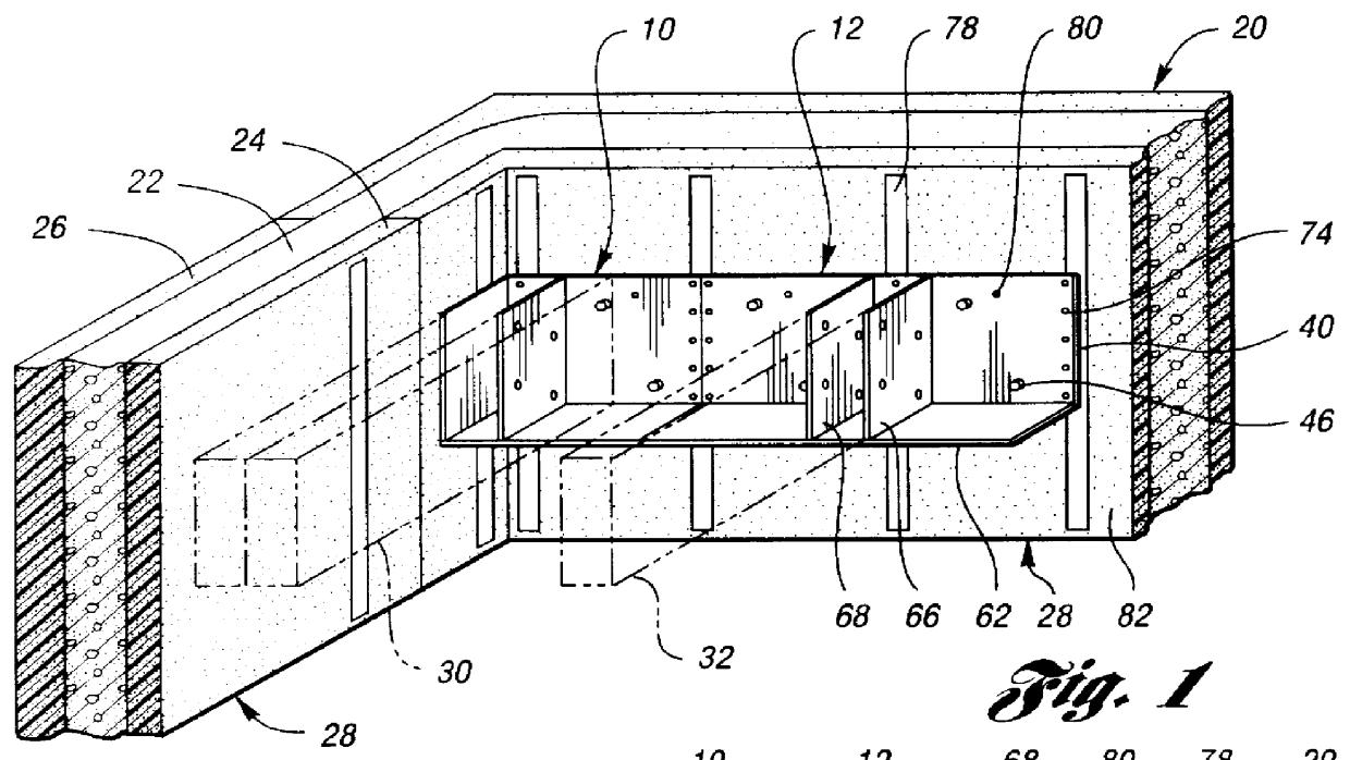
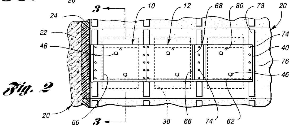
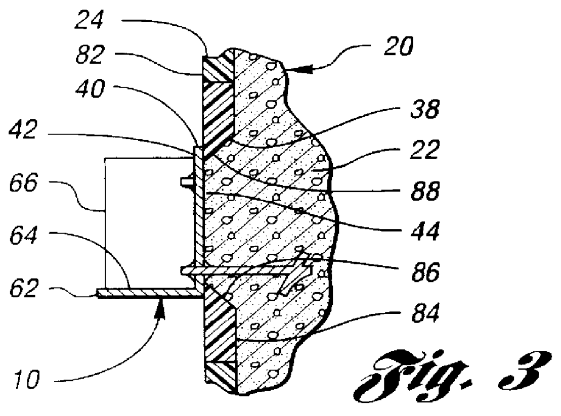
FIGS. 1-10 show five exemplary joist hangers 10,12,14,16,18 in accordance with the invention integrated within a composite wall 20 which is itself formed by pouring a suitable curable material 22, such as concrete, between the interior and exterior foam panels 24,26 of a plurality of interlocked modular preforms 28. By way of example only, a suitable modular wall preform 28 for use with the invention is sold by AAB Building Supplies, Inc. of Ottawa, Canada, under the trademark BLUEMAXX.RTM..

More specifically, FIGS. 1-4 show an adjacent pair of joist hangers 10,12, the first of which is a "left-hand" joist hanger 10 for supporting a single or double rim joist 30, while the second joist hanger 12 supports a single joist 32 along an adjacent span of the wall 20. FIGS. 5-7 show a third joist hanger 14 in accordance with the invention upon which multiple parallel-spaced joists 34 can be hung, and which can conveniently be cut to any desired length. FIGS. 6 and 7 illustrate the ease with ...


PUM


Abstract

A joist hanger includes a thin, flat base whose back side defines a surface area sufficient to cover a rearwardly-tapered through-hole formed in an interior panel of a modular wall preform. The joist hanger includes at least one anchor member on the back side of the base. Each anchor member extends rearwardly from the base into the through-hole to a depth greater the nominal thickness of the first panel. Each anchor member defines an angled deflecting surface such that, with the joist hanger's base secured to the panel so as to cover the through-hole, and with the anchor members extending into and through the through-hole, wall material poured into the preform will be urged by the deflecting surfaces toward the back side of the joist hanger, into the through-hole and around the anchor members, whereby the presence of voids behind the joist hanger is greatly reduced.

Description

The invention relates to joist hangers which may be integrated within composite walls formed of concrete poured between the opposed high-density foam panels of stacked modular wall preforms, and an installation method for such joist hangers.The prior art teaches a method of constructing poured concrete walls in which modular wall preforms, each comprising a pair of high-density foam panels which are maintained in a parallel-spaced relationship by a series of bridging "webs" extending between and through and molded into the panels, are interlockingly stacked together to define a concrete form for the poured concrete wall. With reinforcing steel bars optionally suspended within the assembled wall form, preferably through use of hooks or other retainers provided on each bridging web, the concrete is thereafter poured between the panels to complete the wall.Unlike other known methods of constructing poured concrete walls in which the form's panels are removed from the poured concrete wa...

Claims


Application Information

Patent Timeline
Patent Type & Authority Patents(United States)
IPC IPC(8): E04B1/26
CPCE04B1/2612
Inventor WISE, MICHAEL A.
Owner WISE MICHAEL A
Features
  • Generate Ideas
  • Intellectual Property
  • Life Sciences
  • Materials
  • Tech Scout
  • Unparalleled Data Quality
  • Higher Quality Content
  • 60% Fewer Hallucinations
Learn More