Railway brake shoe backing plate with improved mounting alignment feature

a technology of mounting alignment and brake shoe, which is applied in the direction of brake types, braking elements, braking members, etc., can solve the problems of affecting the proper functioning and structural integrity of the brake shoe, the wear life of the brake shoe and the wheel, and the failure of the brake shoe to bring into proper contact alignment, etc., to achieve the effect of reliable and cost-effective means

Inactive Publication Date: 2000-10-24
RFPC HLDG CORP
View PDF14 Cites 7 Cited by
  • Summary
  • Abstract
  • Description
  • Claims
  • Application Information

AI Technical Summary

Benefits of technology

Accordingly, it is a primary object of this invention to provide a new and improved brake shoe for railway vehicles having improved means thereon for maintaining proper alignment of the brake shoe on the brakehead.

Problems solved by technology

When lateral force is applied to the brake shoe it is therefore often possible for misalignment to result, with the effect that the brake shoe is not brought into proper contact alignment with the wheel of the railway car or locomotive.
This is detrimental to the proper functioning and structural integrity of the brake shoe, and the wear life of the brake shoe and wheel.
Lug arrangements which overlap the external surfaces of the brakehead rather than interlocking with cavities on the brakehead face, have been proposed in the past, but such proposals have not been successful due either to the need for welding several small pieces to the backing plate (which is difficult to do in a reliable and cost effective manner), or due to weakness of the lugs attached to the outer perimeter of the backing plate for this purpose.

Method used


Image

  • Railway brake shoe backing plate with improved mounting alignment feature
  • Railway brake shoe backing plate with improved mounting alignment feature
  • Railway brake shoe backing plate with improved mounting alignment feature

Examples


Embodiment Construction

Prior to proceeding with a detailed description of the subject invention, it is noted that for the sake of clarity, identical components which have identical functions have been identified with identical reference numerals throughout the several views of the attached drawings.

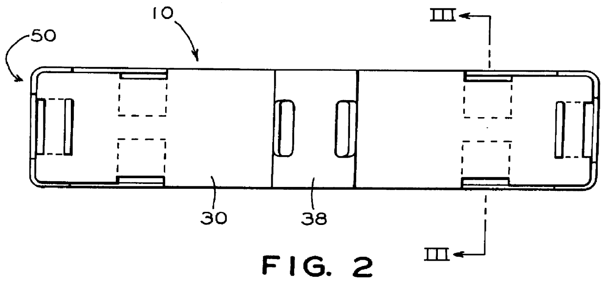
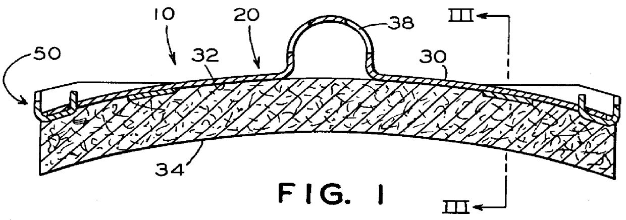
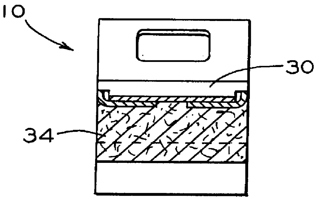
Reference to FIGS. 1-3 will illustrate a brake shoe 10 in accordance with a presently preferred embodiment of this invention incorporating the unique backing plate 20 as better illustrated in FIGS. 5-7. As shown in FIGS. 5-7, the backing plate 20 essentially comprises three separate elements made of a relatively thick and strong sheet steel material, namely an arcuate main plate portion 30, adapted to receive and hold a braking friction material 34 on its concave face 32, with an end plate portion 50 attached to each longitudinal end 38 of the main plate portion 30. The relative configurations of the main plate portion 30 and the two end plate portions 50 are such that they can be joined together to form the un...


PUM


Abstract

A brake shoe for a railway vehicle having a three-piece backing plate formed of a longitudinal main plate portion having a front surface to which a friction material is attached, and an end-plate portion attached to each end of the longitudinal main plate portion. Each of the end plate portions having, a pair of wall members extending generally perpendicularly therefrom adapted to engage not only the edge surface of a the main plate portion but also the edge surfaces of the brakehead to which the three-piece backing plate is attached.

Description

This invention relates generally to brake shoes for railway vehicles; i.e., railway cars and locomotives, and means for maintaining such brake shoes properly aligned with the brakehead and wheel. More particularly, this invention relates to a new and unique three-piece backing plate for railway brake shoes having an improved alignment feature for maintaining alignment of the brake shoe on the brakehead to prevent lateral misalignment and twisting of the brake shoe relative to the longitudinal centerline of the brakehead.Railway brake shoes are typically mounted on brake rigging of railway vehicles by means if a brake shoe key, which passes through a longitudinal slot in the brake shoe holder or "brakehead" of the brake rigging and concurrently through mounting holes of the brake shoe backing plate, such holes being located in a central "keybridge" area of the brake shoe backing plate. The keybridge area of the backing plate is generally formed in such a way that it is adapted to pro...

Claims


Application Information

Patent Timeline
Patent Type & Authority Patents(United States)
IPC IPC(8): F16D65/04F16D65/06
CPCF16D65/062
Inventor KAHR, JOSEPH C.
Owner RFPC HLDG CORP
Why Eureka
Try Eureka