Scanning reader of an optical code placed on an article in movement and a method of scanning said optical code by means of said reader

a scanning reader and optical code technology, applied in the direction of instruments, sensing record carriers, electric discharge lamps, etc., can solve the problems of difficult to make a sufficient number of useful scans and incorrect reading of codes

Inactive Publication Date: 2000-10-24
DATALOGIC
View PDF20 Cites 16 Cited by
  • Summary
  • Abstract
  • Description
  • Claims
  • Application Information

AI Technical Summary

Problems solved by technology

In fact, the reading of the code would be incorrect if the cross-section of the light beam were to cover more than two bars.
The beam of scanning light has a direction oblique with res

Method used


Image

  • Scanning reader of an optical code placed on an article in movement and a method of scanning said optical code by means of said reader
  • Scanning reader of an optical code placed on an article in movement and a method of scanning said optical code by means of said reader
  • Scanning reader of an optical code placed on an article in movement and a method of scanning said optical code by means of said reader

Examples


Embodiment Construction

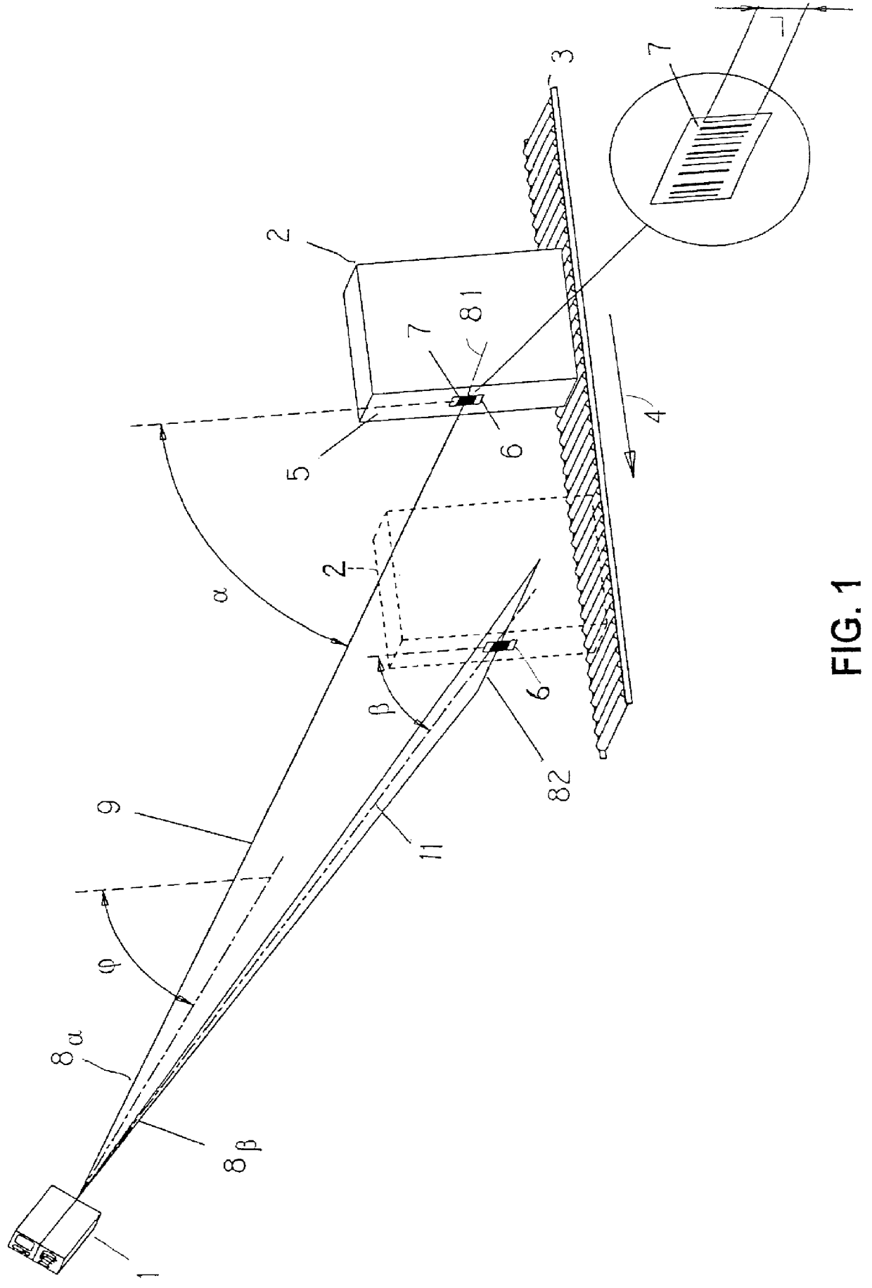
In FIG. 1 there is represented schematically a scanning reader 1 and an article 2 placed on a conveyor belt 3 that makes it move forward in the direction of the reader 1 (arrow 4). On a vertical front wall 5 of the article 2 there is a label 6 on which an optical bar code 7 is printed. The reader 1 emits a light beam 8.sub..alpha. having an axis 9 that lies on a plane inclined by an angle .alpha. with respect to the wall 5. The beam 8.sub..alpha., with inclination .alpha., executes a scanning line 81 substantially horizontal and orthogonal to the bar code 7, that allows an upper area of the wall 5 to be explored. Then, the light beam 8.sub..alpha. is deflected sharply downward and forms a light beam 8.sub..beta. that has axis 11 lying on a plane inclined by an angle .beta. with respect to the wall 5. The beam 8 with inclination .beta. executes a scanning line 82 on the wall 5 also having a substantially horizontal direction that allows a lower area of the wall 5 to be explored.

Suita...


PUM


Abstract

A scanning reader of an optical code placed on a front wall of an article in movement comprises generators that form at least one first and one second light beam lying on planes inclined by a first and by a second prefixed angle ( alpha , beta ) with respect to the front wall so as to explore a first and a second area of the front wall by at least one first and one second scanning line and read the optical code within an overall distance range, along the direction of forward movement of the article, greater than the useful range of reading distance that can be reached by one light beam only.

Description

1. Field of the InventionThis application is based on application No. MI96 A 002595 filed in Italy, the content of which is incorporated hereinto by reference.The present invention relates to a scanning reader of an optical code placed on an article in movement and a method of scanning said optical code by means of said reader.2. Discussion of Prior ArtThe term "optical code" is intended to mean a set of graphic markings (placed on a label or directly on a product or on any other support) bymeans of which a piece of information is coded as a sequence of white areas and black areas or of variously coloured areas, arranged according to one or more directions. Examples of such codes are the bar codes, the two-dimensional codes, the colour codes and the like.Generally, a scanning reader of an optical code placed on an article in movement comprises a source of light capable of generating a beam of coherent light and suitable optical components capable of focusing the light beam on the co...

Claims


Application Information

Patent Timeline
IPC IPC(8): G06K7/10G06K7/00
CPCG06K7/10623G06K7/10861G06K7/10673
Inventor GIROTTI, LORENZO
Owner DATALOGIC
Why Eureka
Try Eureka