Article surveillance system

a technology of surveillance system and article, which is applied in the direction of burglar alarm by hand-portable article removal, burglar alarm mechanical actuation, instruments, etc., can solve the problems of narrow shop exit, "unfriendly" customers, and relatively high price per unit, and the system is less suitable for mass surveillance of articles in the shop

Inactive Publication Date: 2000-10-24
DEMODULATION
View PDF12 Cites 73 Cited by
  • Summary
  • Abstract
  • Description
  • Claims
  • Application Information

AI Technical Summary

Problems solved by technology

Since the detection is made by inductive means, antipilferage systems of this kind suffer from a short detection range of a few meters only, which means that the antipilferage arcs must be arranged close to each other and which in turn makes the shop exit narrow and "unfriendly" for the customers.
A drawback of such a system is the relatively high price per unit due to the complexity of the sensor, thus making the system less suitable for instance for mass surveillance of articles in a shop.
To combine requirements for a long detection range with requirements for a high degree of detection reliability, i.e. a minimum risk of false alarms as well as non-detections, has proven difficult for the known article surveillance systems described above.
For systems with a relatively long detection range, such as for instance the one described above with reference to U.S. Pa...

Method used


Image

  • Article surveillance system
  • Article surveillance system
  • Article surveillance system

Examples


Embodiment Construction

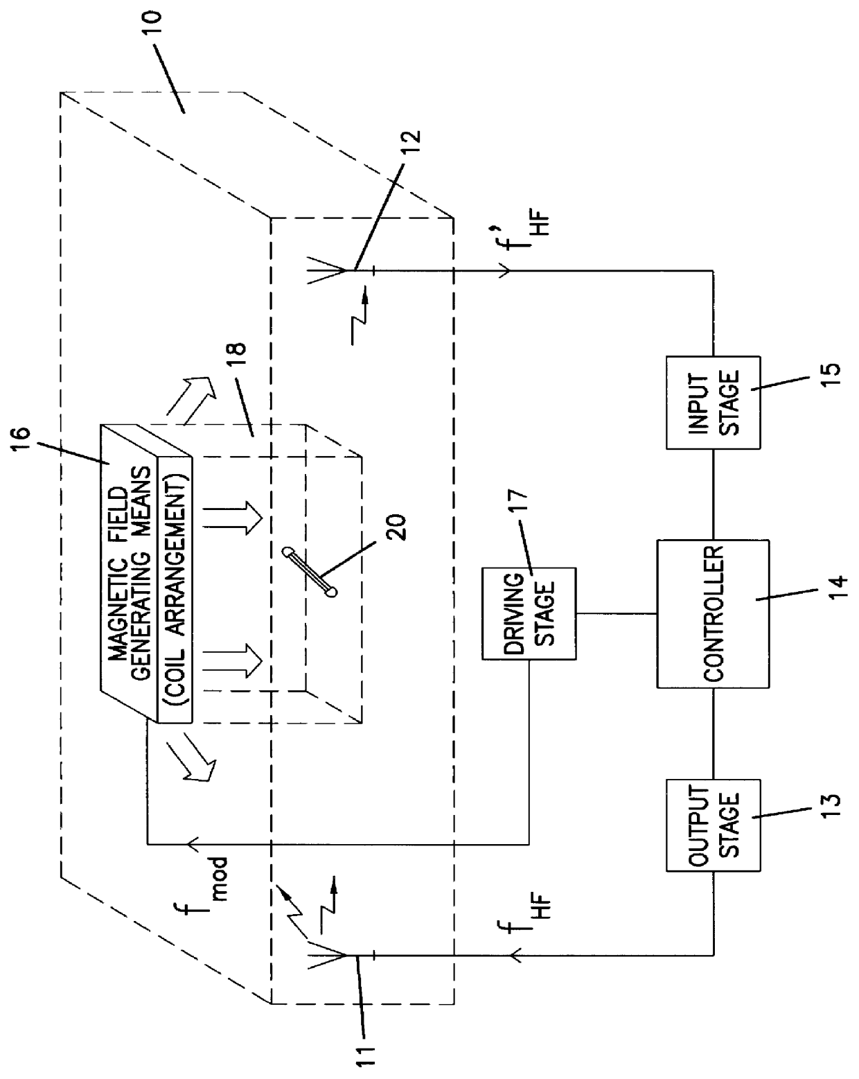
FIG. 1 discloses a schematic block diagram illustrating an article surveillance system according to the present invention. For exemplifying reasons the article surveillance system will throughout the description below be described as an antipilferage system to be used in a shop. However, it should be obvious to any person reading the detailed description below, that the article surveillance system according to the invention may be used also for other purposes than pure antipilferage applications.

The reference numeral 10 represents a part of any given shop, which is located close to the shop exit. Before an exemplary customer steps into the exit area 10 on his way out of the shop, he has already passed some type of cash-desk arrangement, where he is supposed to pay for all the articles picked during his tour around the shop. For the purpose of checking that each customer actually has duly paid for all his articles, at least some, or even all, articles available in the shop assortment...


PUM


Abstract

PCT No. PCT/SE97/00199 Sec. 371 Date Oct. 21, 1998 Sec. 102(e) Date Oct. 21, 1998 PCT Filed Feb. 11, 1997 PCT Pub. No. WO97/29464 PCT Pub. Date Aug. 14, 1997An article surveillance system for detecting the presence of articles in a detection zone (18) has at least one transmitter means (11, 13) and at least one receiver means (12, 15) for transmitting and receiving, respectively, electromagnetic radio-frequency signals in the detection zone or in proximity thereof. Each article is provided with a sensor or marker (20) operating as a transponder for transmitting an electromagnetic radio-frequency reply signal to the receiver means when receiving a signal from the transmitter means. Furthermore, the system has a coil arrangement (16) with driving means (17) for generating a low-frequent magnetic modulating field in the detection zone (18), and a controller (14) operatively connected to the transmitter means (11, 13), the receiver means (12, 15) and the coil arrangement (16, 17). Each sensor (20) is arranged to transmit a reply signal, the amplitude of which is modulated by the magnetic modulating field, and the receiver means is arranged to receive and to demodulate the amplitude-modulated reply signal. The controller (14) is arranged to supply modulating signals (imod) to the coil arrangement (16, 17), to receive the demodulated signals (idemod) from the receiver means (12, 15) and to use the demodulated signals (idemod) when determining the position of the sensor (20) in relation to the detection zone (18).

Description

The present invention relates to an article surveillance system for detecting the presence of articles in a detection zone, comprising at least one transmitter means and at least one receiver means for transmitting and receiving, respectively, electromagnetic radio-frequency signals within the detection zone or in a proximity thereof, each article being provided with a sensor operating as a transponder for transmitting an electromagnetic radio-frequency reply signal to said receiver means when receiving a signal from said transmitter means.DESCRIPTION OF THE PRIOR ARTFor many years now a substantial need for simple and still reliable surveillance systems for monitoring objects or articles within a given area has been noticed in various business and industrial applications. A common example is the electronic shop antipilferage systems, which are available in many different kinds.According to a common kind of electronic article surveillance systems each article is provided with a smal...

Claims


Application Information

Patent Timeline
IPC IPC(8): G01V15/00G08B13/24
CPCG01V15/00G08B13/2442G08B13/2485G08B13/2471G08B13/2445
Inventor TYREN, CARL
Owner DEMODULATION
Why Eureka
Try Eureka