Deck or dock float

a technology for docks and floats, applied in special-purpose vessels, vessel construction, transportation and packaging, etc., can solve the problems of increased manufacturing costs and heavy units, and achieve the effects of less expensive, increased manufacturing costs, and desired light weigh

Inactive Publication Date: 2000-10-31
AGRESSIVE IND
View PDF6 Cites 25 Cited by
  • Summary
  • Abstract
  • Description
  • Claims
  • Application Information

AI Technical Summary

Benefits of technology

Most such float units are foam or buoyancy material additive filled and this creates a particularly heavy unit with increased manufacturing costs due to the material addition.
Applicant provides a

Problems solved by technology

Most such float units are foam or buoyancy material additive filled and this creates a

Method used


Image

  • Deck or dock float
  • Deck or dock float
  • Deck or dock float

Examples


Embodiment Construction

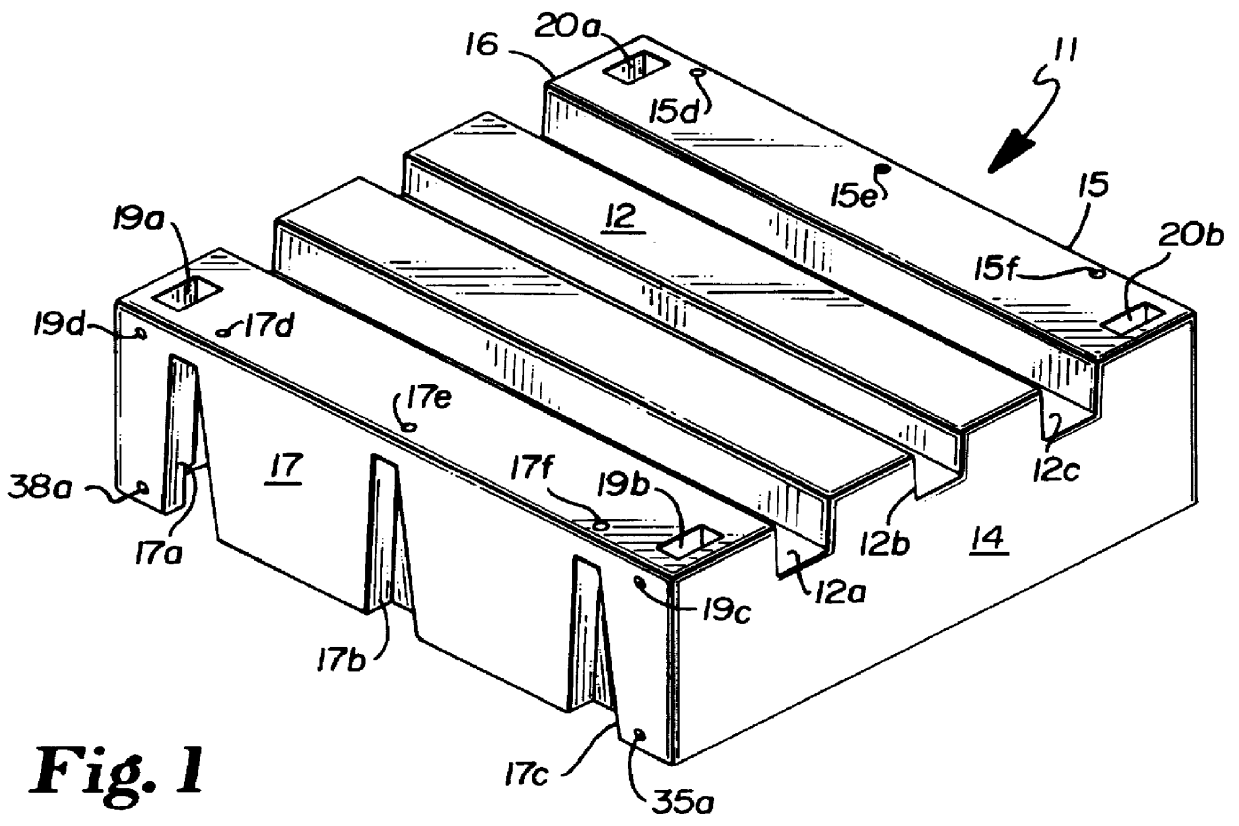
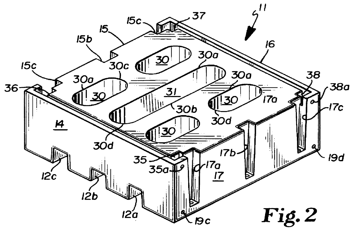
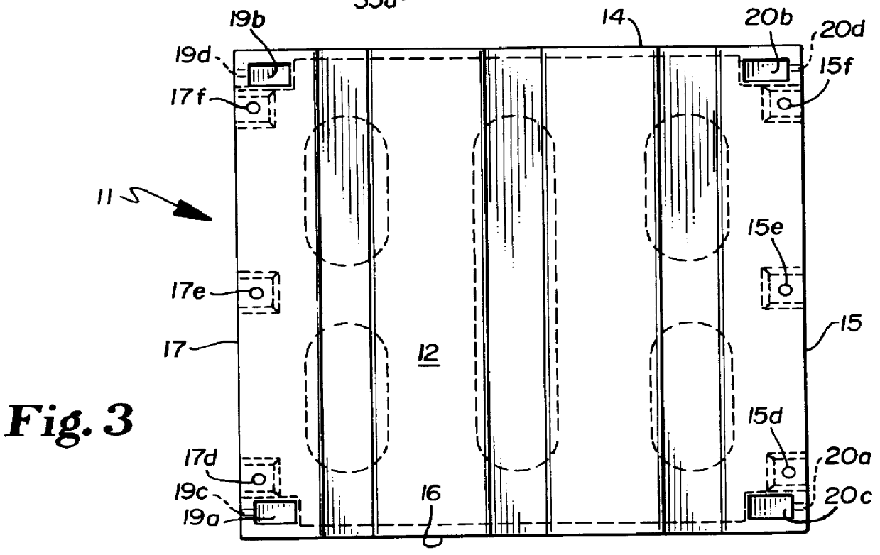
In accordance with the accompanying drawings, the float unit embodying the concepts of the Applicant's invention is generally designated 11 in FIG. 1 and as 51 in FIG. 8 with the various sections shown in the various views being applicable to both forms.

As illustrated in FIGS. 1 and 8, the units 11 and 51 include a generally rectangular top 12, bottom 13 and downwardly extending sides 14, 15, 16, 17 and in FIG. 8 as top 52, bottom 53 and downwardly extending sides 54, 55, 56, 57.

The form illustrated in FIG. 1 will be initially described.

In FIG. 1, top 12 is provided with a plurality of spaced, generally rectangular recesses of which three are illustrated 12a, 12b, 12c extending entirely across the unit and which may be selectively utilized as receptacles for joinder elements extending between successive units or which may be utilized as receptacles for supply lines such as power, gasoline or the like.

As illustrated these recesses 12a, 12b, 12c are arranged in a single, parallel dire...


PUM


Abstract

A float which may be utilized individually or which may be joined to other such floats or used with other elements to provide flotation for a deck or dock unit. Though the particular shapes and attributes of the float may vary for the particular use, the basic float consists of a hollow, preferably rotocast, unit which combines an exterior skin with attachment accommodations having a selectable top surface and a first and second flotation concept. The first flotation is provided by the buoyancy of the hollow structure with the second achieved through a plurality of selectively shaped and positioned cavities extending upwardly from the bottom surface of the float to a location at or adjacent the upper surface of the float. With this dual flotation provision, should the exterior skin of the float be pierced, allowing water to fill the interior thereof, flotation is provided by air entrapment within the formed cavities. The float provides for selective upper surface arrangements dependent upon the desire of the user and may include a flat, or otherwise formed surface.

Description

Applicant has no applications currently on file with the United States Patent and Trademark Office which should be considered in association with the prosecution of this application and is not aware of any pending applications by others which should be so considered.SPONSORSHIPThis application is not made under either any Federal or other sponsorship and is the result of the sole effort of the Applicant.This invention relates generally to water floats and the like and more specifically to a float which may be combined with other similar floats to provide a floating dock, deck surface or support for a deck surface and which is specifically designed to provide two considerations for maintaining flotation which include both a sealed, floating unit and a plurality of air entrapping cavities formed in the bottom surface of such a unit such that if the seal should be broken or a surface of the same be broken or pierced, air entrapment cavities will maintain the unit in buoyed condition.SH...

Claims


Application Information

Patent Timeline
IPC IPC(8): B63B35/34B63B35/38B63B3/00B63B3/06
CPCB63B35/38B63B3/06
Inventor BERQUIST, TOMM A.
Owner AGRESSIVE IND
Why Eureka
Try Eureka