Electronic chassis electro-magnetic interference seal and sealing device

a technology of electromagnetic interference and electronic devices, which is applied in the direction of electrical apparatus casings/cabinets/drawers, electrical apparatus construction details, instruments, etc., can solve the problems of limiting the amount of permitted emi emissions of electronic devices, affecting the performance of devices that act as r.f. receivers such as computers and other electronic devices, and affecting the performance of sensitive devices. , to achieve the effect of minimizing the leakage of electro-magnetic interferen

Inactive Publication Date: 2000-10-31
GATEWAY
View PDF8 Cites 38 Cited by
  • Summary
  • Abstract
  • Description
  • Claims
  • Application Information

AI Technical Summary

Benefits of technology

It is an object of the present invention to minimize Electro

Problems solved by technology

Since the beginning of the use of electrical devices and assemblies, particularly electronic devices such as computers, there has been the issue of Electro-Magnetic Interference (EMI) which can interfere with sensitive devices and receivers of Radio Frequency (R.F.) signals.
EMI can degrade performance of devices that act as R.F. receivers such as computers and other electronic devices.
As EMI can result in the interference or failure of other electrical devices or assemblies located nearby, the Federal Communications Commission (FCC) has established st

Method used


Image

  • Electronic chassis electro-magnetic interference seal and sealing device
  • Electronic chassis electro-magnetic interference seal and sealing device
  • Electronic chassis electro-magnetic interference seal and sealing device

Examples


Embodiment Construction

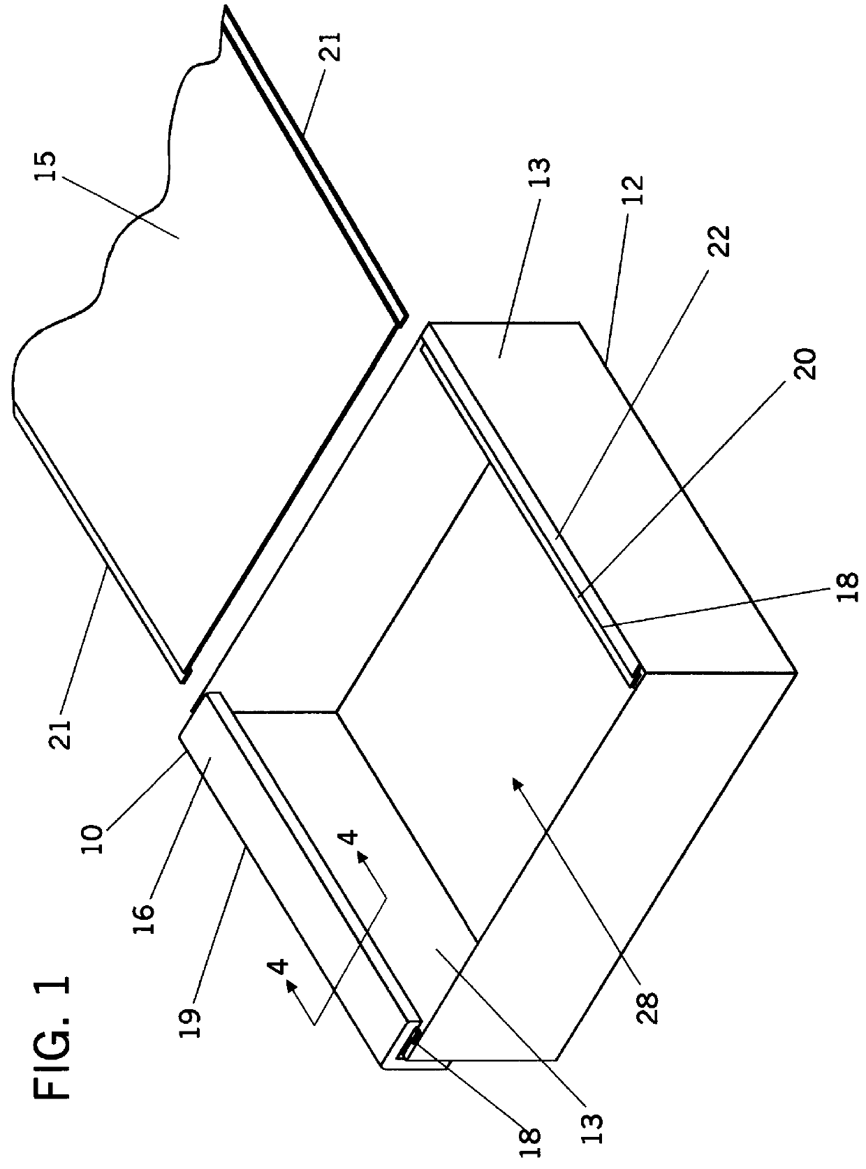
One embodiment of the present invention is illustrated in FIG. 1. The embodiment shown comprises an enclosure 10 fabricated of two sub-assemblies, the chassis base 12 and chassis lid 14.

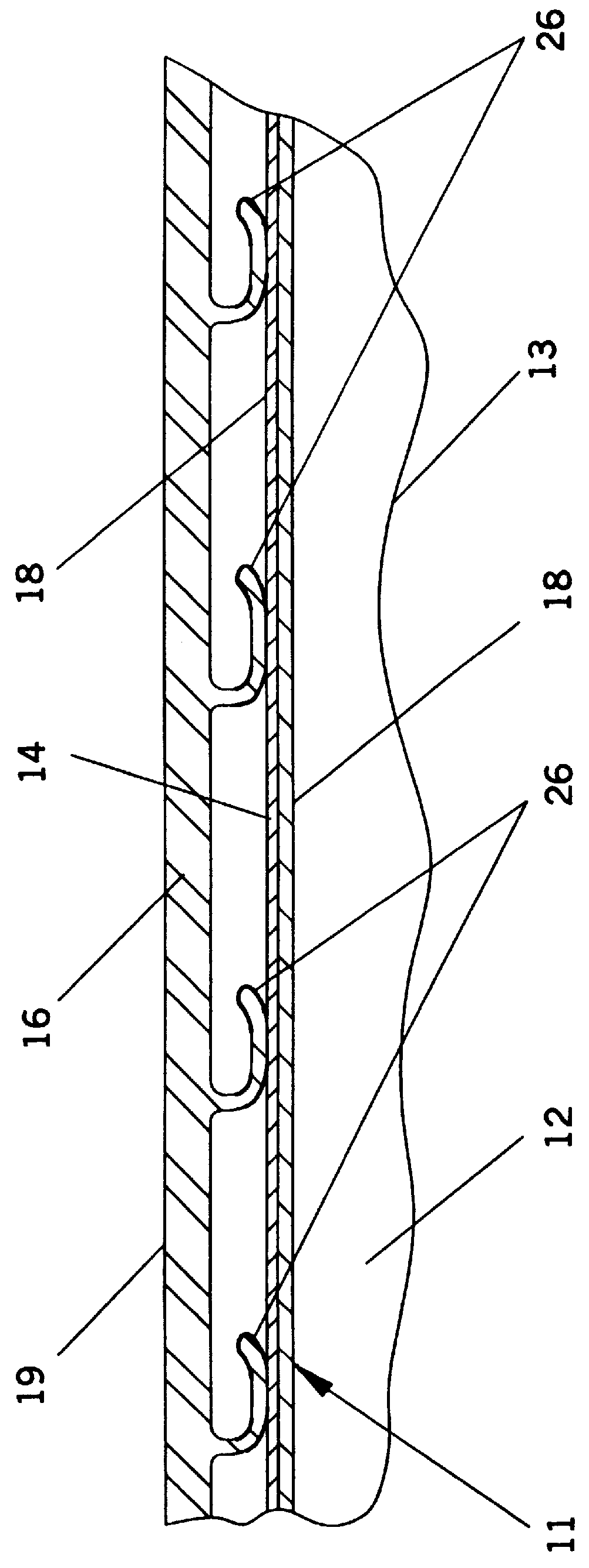
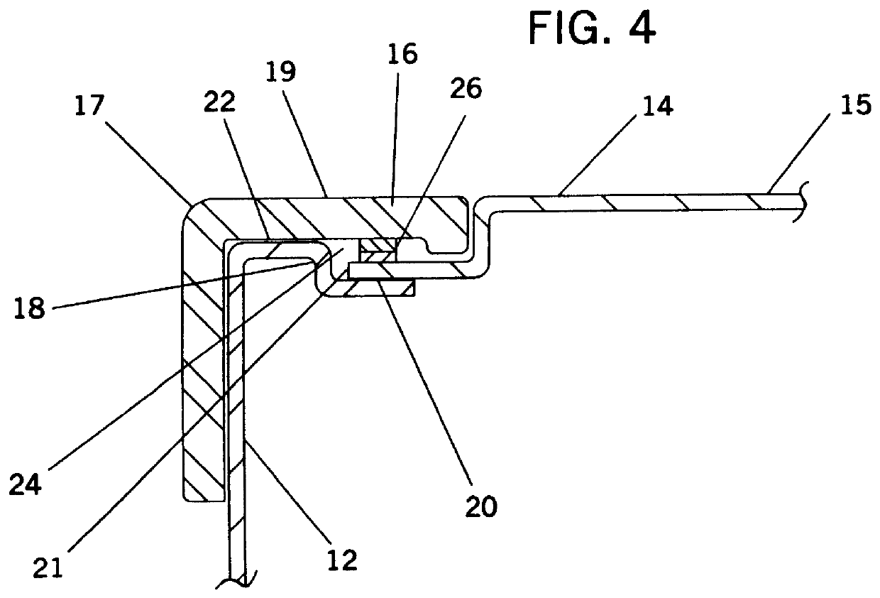
The chassis base 12 has an open or missing side 28 which may be closed by chassis lid 14. Chassis lid 14 is shown disengaged. Partially extending inward from the walls 13 of the chassis base 12 are support and engagement flanges 18. The preferred shape and design of the support and engagement flanges 18 can best be seen in FIG. 3. It should be noted that surface 22 of flange 18 may be in or close to the same plane as the top edge of chassis base 12, and that surface 20 of flange 18 is slightly recessed from the horizontal plane in which surface 22 lies. This recession can be of a depth dependent on the thickness of the materials used, but should only be as deep as necessary so that when lid 14 is slidably engaged and rests on flanges 18, the top surface 15 of lid 14 is in the same plane as the top su...


PUM


Abstract

An improved apparatus for reducing and minimizing Electro-Magnetic Interference (EMI) leakage from electrical devices or assemblies contained in a cabinet or other similar enclosure such as a computer system unit. Spring fingers or arms contained in the enclosure force two adjacent faces of the enclosure components together to create an EMI minimizing seal.

Description

The present invention relates to an improved device and method of preventing Electro-Magnetic Interference (EMI) leakage from electrical devices and more particularly to assemblies where elements of a chassis and lid are forced together for assembly and to form an EMI seal.Since the beginning of the use of electrical devices and assemblies, particularly electronic devices such as computers, there has been the issue of Electro-Magnetic Interference (EMI) which can interfere with sensitive devices and receivers of Radio Frequency (R.F.) signals. EMI can degrade performance of devices that act as R.F. receivers such as computers and other electronic devices. Therefore, there is a need to prevent or minimize EMI leakage from the chassis or housing of the electrical device. As EMI can result in the interference or failure of other electrical devices or assemblies located nearby, the Federal Communications Commission (FCC) has established standards which severely limit the amount of permi...

Claims


Application Information

Patent Timeline
IPC IPC(8): H05K9/00
CPCH05K9/0016
Inventor RAPAICH, MARKZAPPACOSTA, ELISA E.
Owner GATEWAY
Why Eureka
Try Eureka