Spout assembly, spout assembly manufacturing apparatus and package with spout assembly

a technology of spout assembly and manufacturing apparatus, which is applied in the direction of caps, liquid handling, and closures using stoppers, etc., and can solve the problems of troublesome spout closing, inside of the cap exposed outside entering the spout, and undesirable surface layer of less than 9 mu.m

Inactive Publication Date: 2000-11-07
DAI NIPPON PRINTING CO LTD
View PDF24 Cites 48 Cited by
  • Summary
  • Abstract
  • Description
  • Claims
  • Application Information

AI Technical Summary

Problems solved by technology

Therefore, when putting the cap separated from the spout on the spout again, the inside of the cap exposed outside enters the spout, which is unsanitary.
When putting the cap separated from the spout on the spout to close the spout, the cap needs to be inverted, which requires a troublesome spout closing action.
A surface layer of a thickness less than 9 .mu.m is undesirable because such a surface layer has insufficient strength, poor printability and inferior fitness for lamination.
A surface layer of a thickness greater than 50 .mu.m is undesirable because such a surface layer has an excessive strength for a small pouch, which is to be provided by the present invention, and such an excessively thick surface layer is costly.
An intermedi

Method used


Image

  • Spout assembly, spout assembly manufacturing apparatus and package with spout assembly
  • Spout assembly, spout assembly manufacturing apparatus and package with spout assembly
  • Spout assembly, spout assembly manufacturing apparatus and package with spout assembly

Examples


Embodiment Construction

Examples of the ninth embodiment will be described with reference to FIGS. 35 to 38.

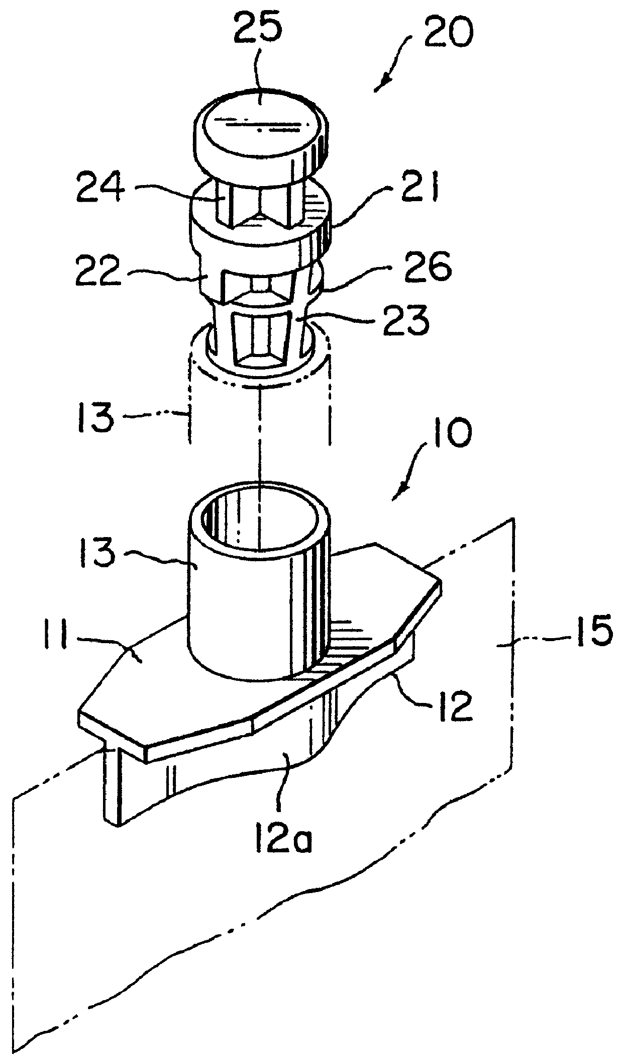
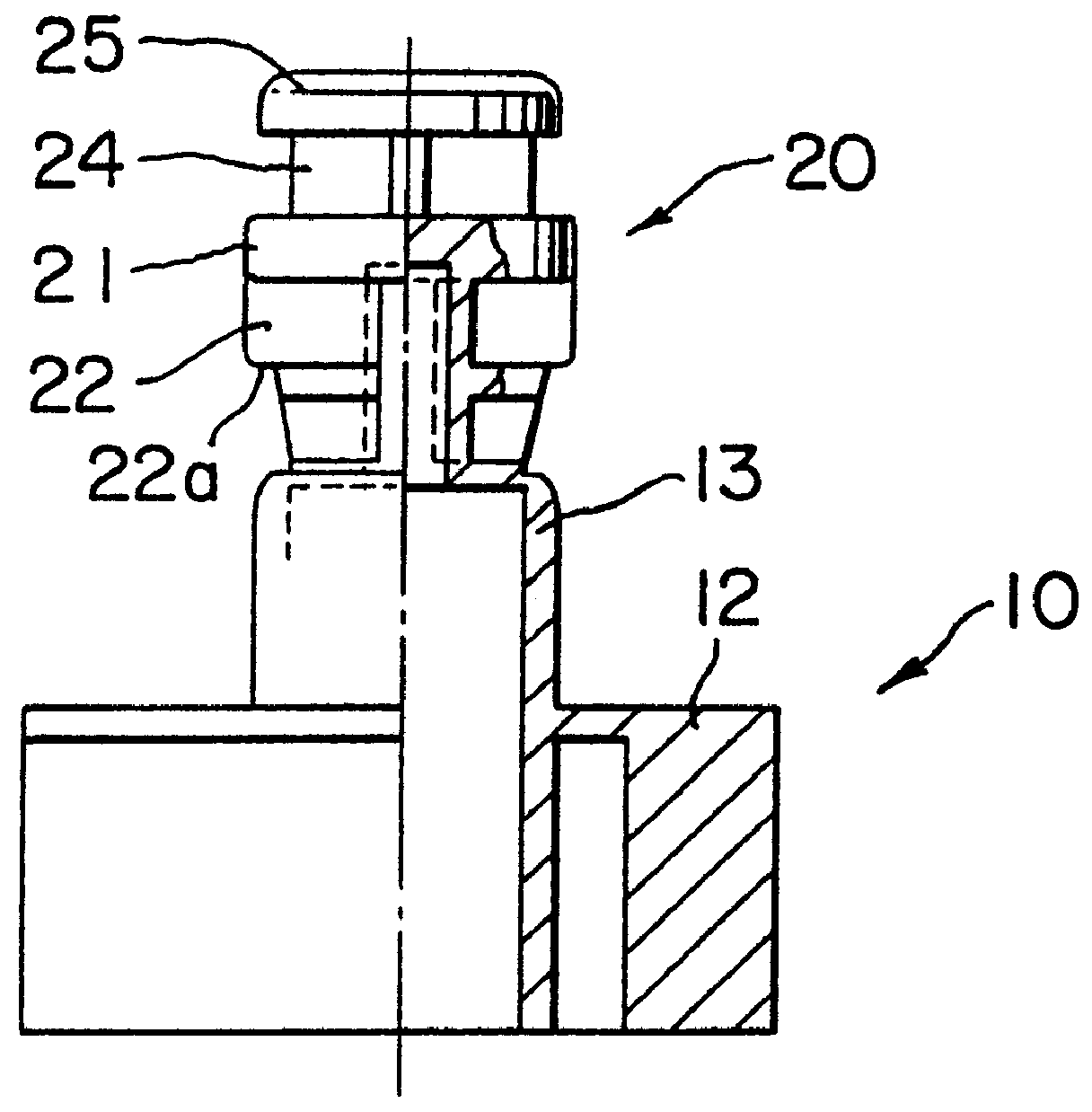
Sample spout assemblies (10, 20) were made of a polypropylene (PP), a low-density polyethylene (LDPE) or a linear low-density polyethylene (LLDPE), for example, the LLDPE, and the breaking strength of the sample spout assemblies (10, 20) was measured.

Different substances were filled in sample pouches 50, 51 and 52 provided with the spout assembly, and the sealing strength of the sample pouches 50, 51 and 52 were measured.

When measuring the breaking strength of the sample spout assembly (10, 20), the sample spout assembly (10, 20) was held by the flange 11 by a vise 61 as shown in FIG. 36, and then the cap 20 of the sample spout assembly (10, 20) was pulled by a push-pull gage as shown in FIG. 35 to measure the breaking strength of the sample spout assembly (10, 20).

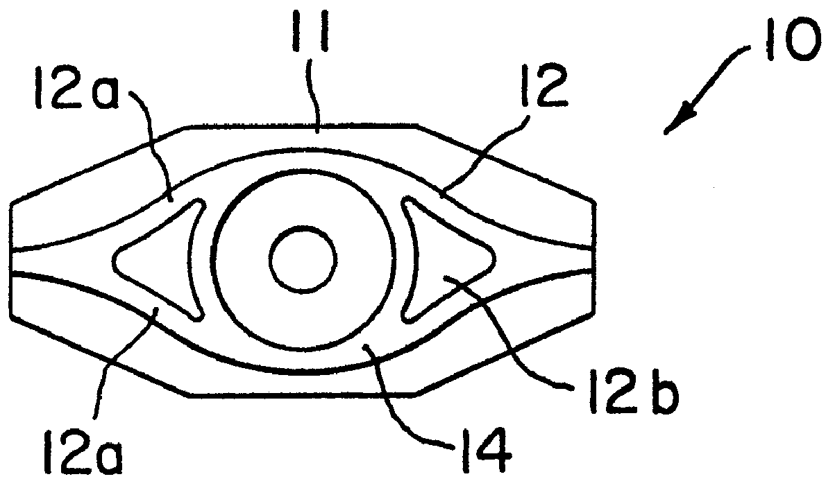
When measuring the sealing strength, the pair of attaching plates 12a of the sample spout assemblies (10, 20) were divided into six secti...


PUM

PropertyMeasurementUnit
Weightaaaaaaaaaa
Weightaaaaaaaaaa
Weightaaaaaaaaaa

Abstract

A spout assembly comprises a spout (10) and a cap (20). The spout has a cylindrical outer tube (13) to be placed outside a package (15) and a base (12) to be bonded to the inner surface of the package (15). The cap (20) is separably connected to an extremity of the cylindrical outer tube (13) coaxially with the cylindrical outer tube (13) in a position in which the cap (20) is pushed into the cylindrical outer tube (13).

Description

The present invention relates to a sanitary spout assembly having a spout and a cap, an apparatus for manufacturing a spout assembly, and a package provided with a spout assembly.RELATED ARTSpout assemblies each having a spout to be attached to a package, and a cap to be put on the spout, formed integrally with the spout are disclosed in JP-A Nos. 5-162756 and 5-229566.The spout assembly disclosed in JP-A No. 5-162756 has a spout to be attached to a package, and a cap for closing the spout. The cap is formed integrally with the spout in an upside-down position. The integral formation of the spout and the cap is effective in reducing the manufacturing cost of the spout assembly and enables the omission of work for putting the cap on the spout.As mentioned above, there is a known spout assembly having a spout and a cap formed integrally with the spout. In this known spout assembly, however, the cap is connected in an upside-down position to the spout with its inside exposed outside. T...

Claims


Application Information

Patent Timeline
IPC IPC(8): B29C45/00B29C45/36B65D75/58B65D75/52B65D33/38
CPCB29C45/006B29C45/36B65D75/58B65D75/5883B29C2045/0049B65D2575/583B29C2045/0065
Inventor UEMATSU, HIROSHI
Owner DAI NIPPON PRINTING CO LTD
Why Eureka
Try Eureka