Bracket for suspended ceiling tiles

a ceiling tile and bracket technology, applied in the field of brackets for suspended ceiling tiles, can solve the problems of affecting the installation of the bracket, etc., and achieve the effect of convenient removal and installation

Inactive Publication Date: 2000-11-14
DALLAIRE MICHEL
View PDF6 Cites 53 Cited by
  • Summary
  • Abstract
  • Description
  • Claims
  • Application Information

AI Technical Summary

Benefits of technology

It is the gist of the present invention to provide a bracket for supporting aesthetic ceiling tiles that allows easy removal and installation of the tiles.

Problems solved by technology

However, this is often much more complex than it may seem, since there are often a large number of wires and miscellaneous gear over the ceiling tiles, including light casings, air ducts, phone and electric wires, etc . . . . Thus, the space required to rotate and tilt the ceiling tile often lacks, and the tile must be forced through its opening by slightly resiliently deforming the tile and sliding it through the surrounding rails.
Since these tiles are often made of semi-rigid cardboard-like material, it is only very slightly flexible, and the removal / installation operations effectively result in damaging the fragile tile due to its frictional sliding engagement against the surrounding rails.
Another disadvantage of these suspended ceiling rails and tiles is that it is difficult to modify the already installed suspended ceiling configuration, such as in showrooms or the like wherein the ceiling configuration can be modified rather frequently.

Method used


Image

  • Bracket for suspended ceiling tiles
  • Bracket for suspended ceiling tiles
  • Bracket for suspended ceiling tiles

Examples


Embodiment Construction

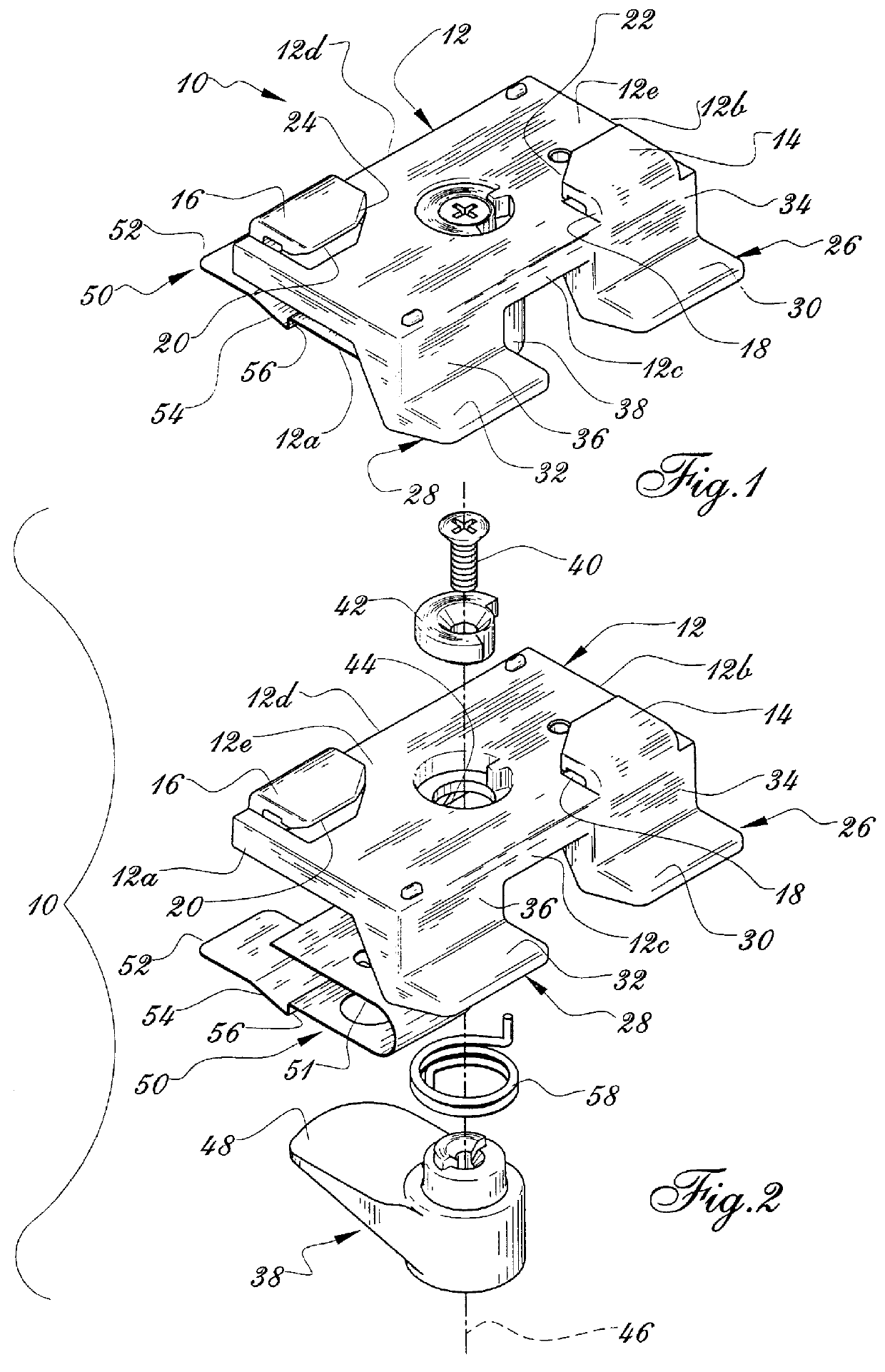
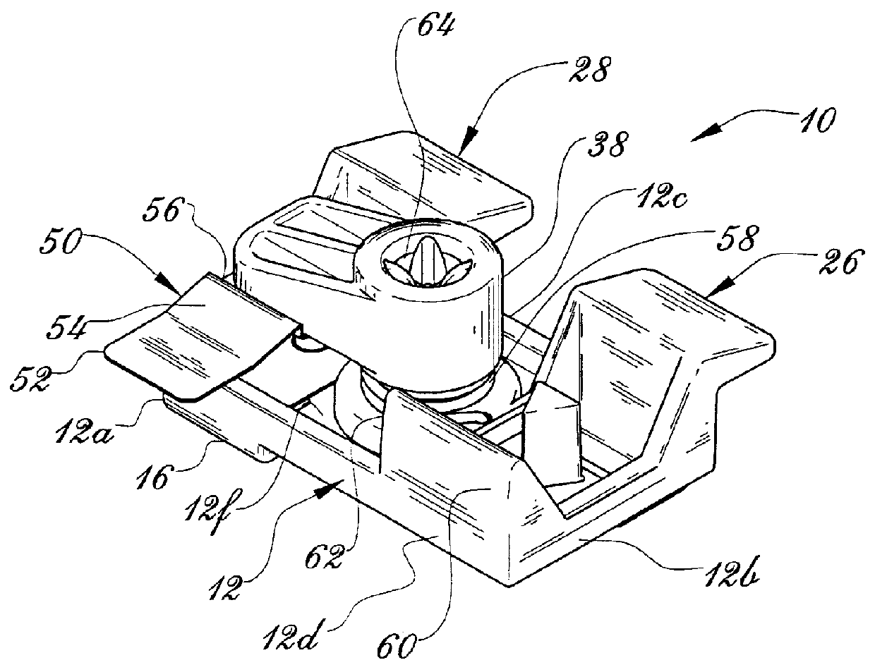
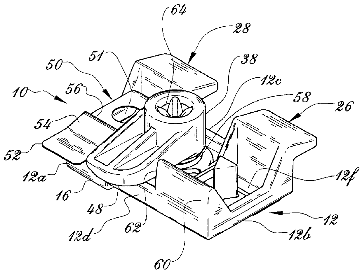
FIGS. 1-4 show a bracket 10 according to the invention. Bracket 10 comprises a substantially flat and rectangular main body 12 defining first and second opposite ends 12a, 12b, first and second opposite sides 12c, 12d and an upper and a lower opposite surfaces 12e, 12f.

Main body 12 comprises, on its upper surface 12e, a pair of upwardly oriented lips 14, 16 located on opposite sides and opposite ends of main body 12, i.e. lip 14 is located along first side 12c near second end 12b and lip 16 is located along second side 12d near first end 12a. Lips 14, 16 could be located on any of the two pairs of opposite corners thus defined, i.e. they could alternately be located as follows: lip 14 could be located along second side 12d near second end 12b, while lip 16 would then be located along first side 12c near first end 12a. Lips 14, 16 form inwardly oriented elbowed plates which come into close parallel relation with the main body upper surface 12e, so as to define slots 18, 20 between li...


PUM


Abstract

A number of ceiling rails are installed under the structural ceiling of a room in a selected array, in a configuration to provide openings between the rails to fit therein ceiling tiles. Brackets are used to support the tiles, the brackets being removably attached to the rails. At least one bracket is used on each side of a tile. The bracket comprises a pair of slots that allow it to be snapped onto the rail, and has a pair of integral laterally projecting load-bearing plates which support a first tile on one side and a pivotable supporting finger which can support a second tile on its opposite side. The pivotable finger pivots between an inoperative position in which is extends along the length of the bracket without laterally projecting therefrom, and an operative position in which it laterally projects beyond the side edge of the bracket. In this operative position, it may support a ceiling tile. A coil spring continuously biases the finger towards its operative position, while a spring blade catch prevents it from being pivoted into its operative position, until a tile to be supported by the finger is pushed by a work person to abut against the catch and releases the finger into pivotal displacement, towards its operative position, in which it will support the tile abutting against the catch.

Description

The present invention relates to suspended ceilings, and more particularly to a bracket for suspended ceiling tiles.It is known to provide a plurality of removable ceiling tiles which are installed in adjacent fashion as an aesthetic ceiling spacedly underneath the structural ceiling of a room, whereby the aesthetic ceiling does not support any structural load. Water conduits, electrical wires and other miscellaneous building equipment can be located between the aesthetic ceiling tiles and the structural ceiling, without being apparent from the room per se. Light material, such as electric or phone wires or the like, can even be supported by the aesthetic ceiling tiles.To support the ceiling tiles, an array of perpendicular thin metallic or plastic rails is often used, with a number of rectangular openings being defined between the rails to receive the tiles. Each tile is thus supported by gravity on its four sides by the rails, with each rail having a pair of parallel adjacent hori...

Claims


Application Information

Patent Timeline
Patent Type & Authority Patents(United States)
IPC IPC(8): E04B9/22E04B9/24E04B9/26
CPCE04B9/26E04B9/247
Inventor DALLAIRE, MICHEL
Owner DALLAIRE MICHEL
Why Eureka
Try Eureka