Apparatus and method for precision grinding face gear

Inactive Publication Date: 2000-11-14
THE BOARD OF TRUSTEES OF THE UNIV OF ILLINOIS
View PDF18 Cites 36 Cited by
  • Summary
  • Abstract
  • Description
  • Claims
  • Application Information

AI Technical Summary

Problems solved by technology

Face gears are widely used in low power applications, but often are not strong enough for use in high power applications.
This machining process, however, is not suitable for use on a case-hardened face gear.
Additionally, the hob teeth 30 are not prop

Method used


Image

  • Apparatus and method for precision grinding face gear
  • Apparatus and method for precision grinding face gear
  • Apparatus and method for precision grinding face gear

Examples


Embodiment Construction

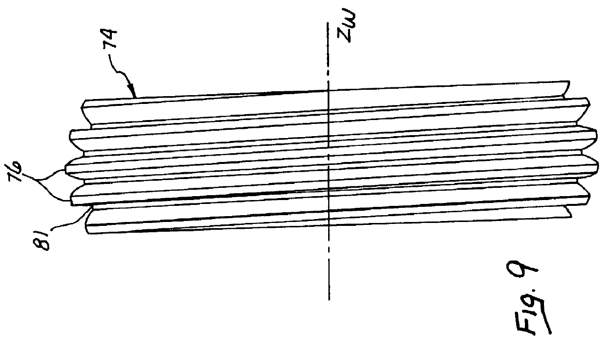
Turning to FIG. 5, a grinding worm 54 according to the presently preferred embodiment is illustrated on the face gear 112. The grinding worm 54 rotates about a grinding worm z-axis Z.sub.W with a grinding worm rotational velocity .omega..sub.W. The grinding worm further comprises a grinding worm x-axis X.sub.W and a grinding worm y-axis Y.sub.W. A plurality of grinding worm teeth 55 contact the face gear 12 as the grinding worm 54 rotates with rotational velocity .omega..sub.W, the grinding worm teeth travel within the face gear gaps 116 to thereby rotate the face gear 112 with the face gear rotational velocity .omega..sub.g. The face gear teeth 114 fit between the grinding worm teeth 55. A single, spiral gap runs along the outer perimeter of the grinding worm 54 between the grinding worm teeth 55. This spiral gap serves to progress the grinding worm 54 over the various face gear teeth 114. Specifically, as the grinding worm 54 rotates with rotational velocity .omega..sub.W, a given...


PUM

PropertyMeasurementUnit
Lengthaaaaaaaaaa
Perimeteraaaaaaaaaa

Abstract

A precision grinding apparatus includes a grinding worm for precision grinding a case-hardened face gear. A shaper is first placed into contact with a face gear, to thereby shape a surface of the face gear into a plurality of face gear teeth. The shaper is then removed, and the face gear is case hardened. The grinding worm is disposed in a normal orientation to the case-hardened face gear and includes a spiral tooth extending along a perimeter of the grinding worm. The spiral tooth of the grinding worm is adapted to contact and precision grind the case-hardened gear. A dressing tool includes a protrusion for contacting the spiral tooth of the grinding worm, as the spiral tooth contacts and precision grinds the case-hardened face gear. The dressing tool thus maintains the shape of the grinding worm to within a desired tolerance range.

Description

The present invention relates generally to the manufacture of face gears and, more particularly, to a face gear grinding apparatus having both a worm-shaped wheel and a dressing tool for use on the worm-shaped wheel.DESCRIPTION OF RELATED ARTFace gears are widely used in low power applications, but often are not strong enough for use in high power applications. Present manufacturing methods for cutting face gear teeth incorporate hobs or shapers. FIG. 1 illustrates a face gear 12 having face gear teeth 14 and face gear gaps 16. A shaper gear 18 comprises shaper gear teeth 21 and shaper gear gaps 23. The shaper gear 18 rotates about a shaper gear axis of rotation Z.sub.S with a shaper gear rotational velocity .omega..sub.S. The face gear 12 rotates about a face gear axis of rotation Z.sub.g with a face gear rotational velocity .omega..sub.g. As the shaper gear 18 rolls over the face gear 12, the shaper gear teeth 21 and the shaper gear gaps 23 form the face gear gaps 16 and the face ...

Claims


Application Information

Patent Timeline
IPC IPC(8): B23F23/00B23F23/12B24B53/06B24B53/075
CPCB23F15/06B24B53/075B23F23/1225
Inventor LITVIN, FAYDOR L.CHEN, YIH-JENHEATH, GREGORY F.SHETH, VIJAY J.CHEN, NINGXIN
Owner THE BOARD OF TRUSTEES OF THE UNIV OF ILLINOIS
Why Eureka
Try Eureka