Ball joint

a ball joint and ball head technology, applied in the direction of pivots, bearing components, shafts and bearings, etc., can solve the problems of difficult lubricant flow between the bearing seat and the ball head, inability to achieve frictional compensation and absorption of dimensional tolerances, and inability to achieve the effect of distributing efficiently and slipping more easily

Inactive Publication Date: 2000-11-28
SOMIC ISHIKAWA INC
View PDF8 Cites 24 Cited by
  • Summary
  • Abstract
  • Description
  • Claims
  • Application Information

AI Technical Summary

Benefits of technology

In order to solve the above problem, an object of the present invention is to provide a ball joint which permits a lubricant to spread efficiently over nearly the entire ball head portion. The

Problems solved by technology

In this configuration, it is difficult for the lubricant to flow between the bearing seat and the ball head portion.
A space portion which occupies virtually the e

Method used


Image

  • Ball joint
  • Ball joint
  • Ball joint

Examples


Embodiment Construction

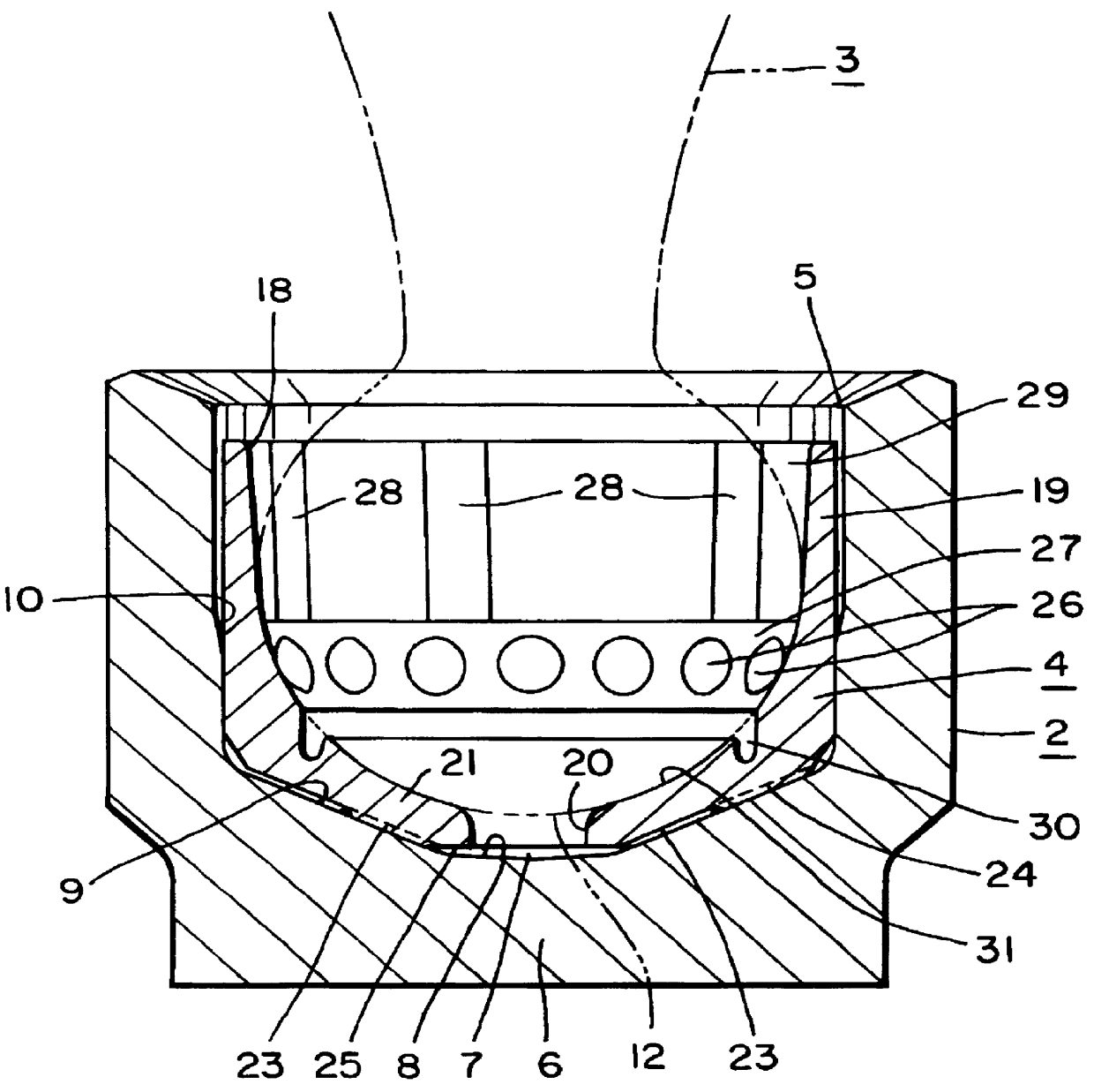
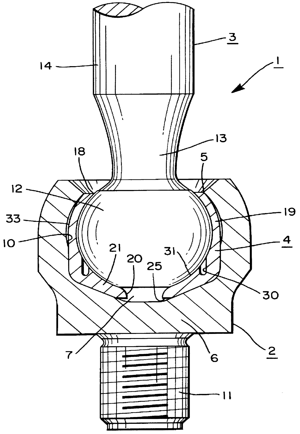
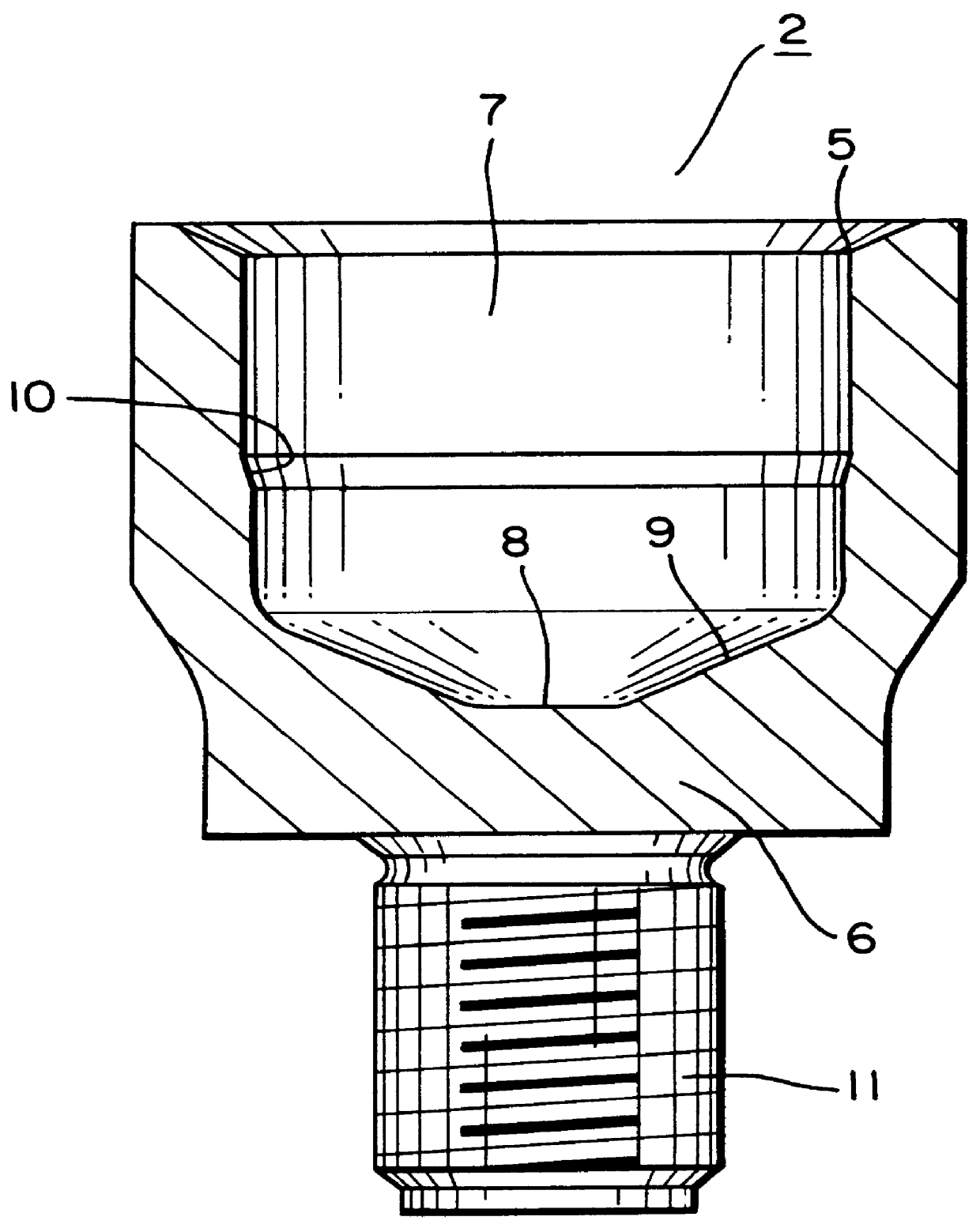
Referring to FIGS. 1 through 3, a ball joint 1 includes a metal cylindrical housing 2, a metal ball stud 3 and a bearing seat 4 made of synthetic resin. The ball joint 1 may be used in the steering system or the suspension mechanism of an automobile, especially at the rack shaft end of the tie rod of a rack-and-pinion steering device.

The housing 2 has an opening 5 and an inner chamber 7, which has a bottom portion 6 located opposite the opening 5. The inner chamber 7 has a generally cylindrical shape with a bottom before it is assembled in a ball joint. A conical face portion 8 is an approximately conical indentation that is formed at the center of the bottom portion 6 of the inner chamber 7 of the housing 2. A generally arc-shaped seating face portion 9 is formed around the conical face portion 8 as an integral, continuous body therewith. A step portion 10 is formed around the wall of the opening 5 with a diameter that tapers outward toward the opening 5. An external threaded porti...


PUM


Abstract

Sliding contact portions on an inner surface of a bearing seat slidably support a ball head of a ball stud in a housing. Spaces between one or more of the sliding contact portions contain lubricant reserves. Load receiving portions on the outer surface of the bearing seat facing the housing also support the load placed on the ball stud. Protruding portions on the sliding contact portions decrease contact surface area and permit lubricant to cover nearly the entire ball head surface. The load receiving portions and sliding contact portions, including the protruding portions, deform to absorb repeated heavy loads while maintaining friction compensation and stable torque. The ball joint has an improved ability to compensate for dimensional tolerances, which facilitates component manufacture. The load withstanding ability, lubrication efficiency and durability of the ball joint are thus improved.

Description

The present invention relates to a ball joint including a housing, a ball stud, and a bearing seat. The ball stud has a ball head portion integrally formed with a stud portion and the bearing seat slidably envelops the ball head portion of the ball stud. The ball stud and bearing seat combination is placed into an inner chamber of the housing through an opening. A lubricant introduced into the inner chamber of the housing permits the ball head portion to slide within the bearing seat.Japanese Patent Laid-open No. 1995-269557 discloses an example of the type of ball joint described above.The ball joint disclosed in Japanese Patent Laid-open No. 1995-269557 includes a bearing seat composed of material that is both elastic and rigid. A plurality of load receiving portions and indented portions are formed on the outer surface of the bearing seat that faces the inner chamber of the housing. The load receiving portions and the indented portions are formed alternately and adjacent with eac...

Claims


Application Information

Patent Timeline
IPC IPC(8): F16C11/06F16C11/08F16C33/08
CPCF16C11/0638F16C11/068F16C11/0685Y10T403/32778Y10T403/32737Y10T403/32721
Inventor ODA, TAKAHIROSUZUKI, KEIICHIRO
Owner SOMIC ISHIKAWA INC
Why Eureka
Try Eureka