Pipe joint

a technology for pipes and joints, applied in the direction of hose connections, screw threaded joints, pipe joints, etc., can solve the problems of abutment shoulder loading, ineffective positioning and feeling functions, plastic deformation in the shoulder region, etc., and achieve the effect of absorbing the bulk of threads

Inactive Publication Date: 2000-12-05
MANNESMANN AG
View PDF11 Cites 86 Cited by
  • Summary
  • Abstract
  • Description
  • Claims
  • Application Information

AI Technical Summary

Problems solved by technology

Axial tension can eliminate the prestressing in the abutment, and thus the positioning and sealing action thereof, and axial compression can result in plastic deformation in the shoulder region and, in the case of subsequent tensile loading, can render the positioning

Method used


Image

  • Pipe joint
  • Pipe joint
  • Pipe joint

Examples


Embodiment Construction

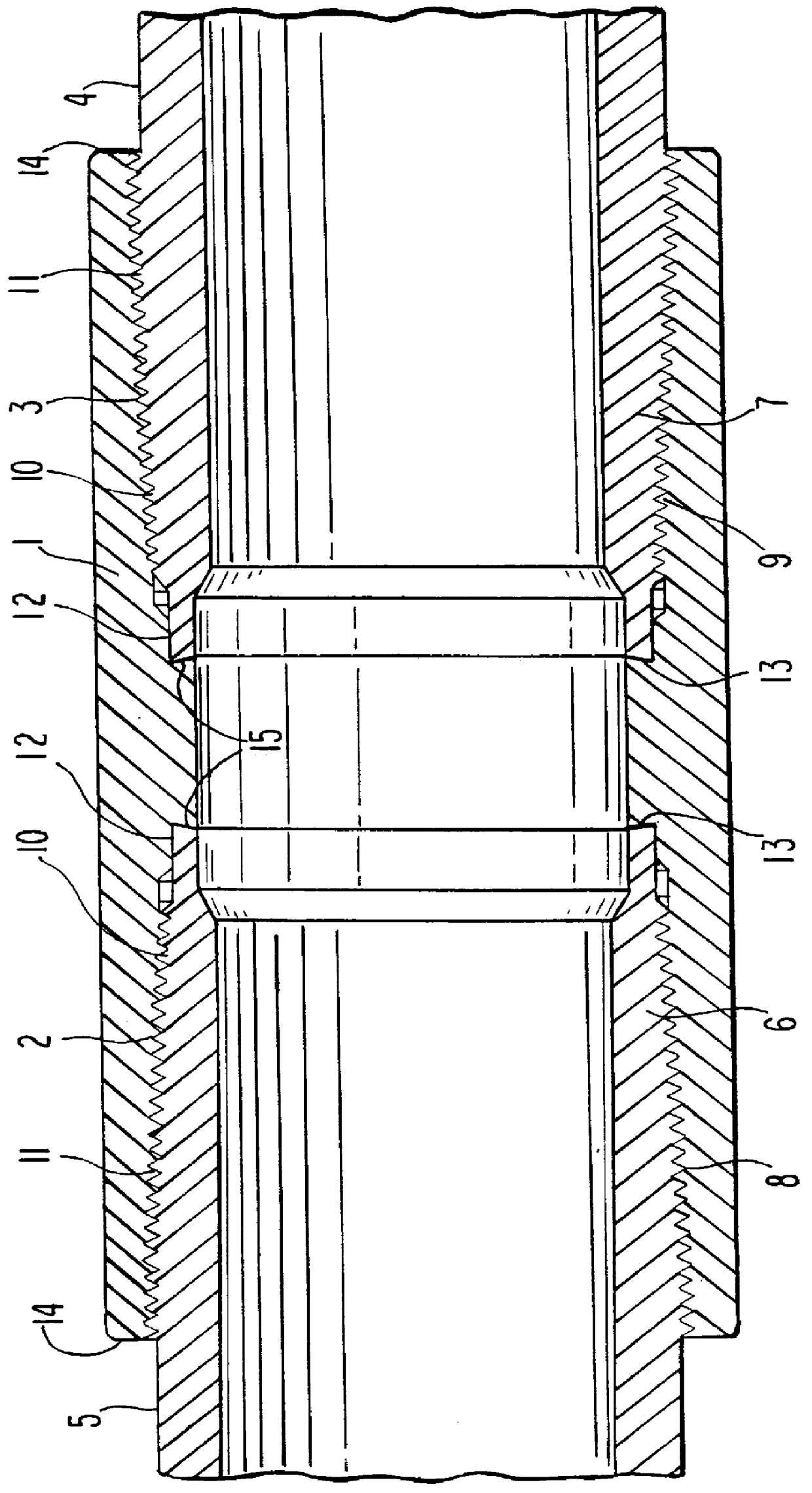
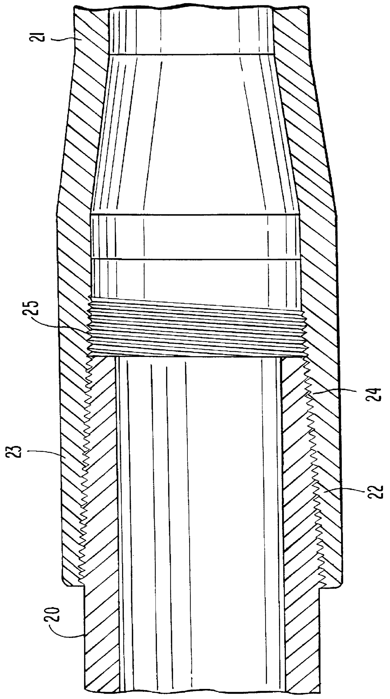
Referring now to the drawings, FIGS. 1 and 2 illustrate pipe joints configured in accordance with the present invention. Specifically, FIG. 1 illustrates a pipe joint with a sleeve and FIG. 2 illustrates a pipe joint in the form of an integral connection. The pipe joint of FIG. 1 comprises a sleeve 1, which is provided with two conically designed threaded sections 2, 3 and, in the central region, has on both sides in each case a sealing seat 12 and an abutment 13. The details of the sealing seat and abutment are not illustrated here since they are not essential to the invention. The two pipes 4, 5 which are to be connected are designed in the end region as a spigot element 6, 7 and have threaded sections 8, 9, which are complementary to the thread of the sleeve 1 and are likewise of conical design. The threaded sections 2 and 3 of the sleeve 1 end at sleeve-face thread ends 11 so that the sections of the internal surface of the sleeve I between the sleeve-faced thread ends 11 and a ...


PUM


Abstract

PCT No. PCT/DE95/01059 Sec. 371 Date Apr. 2, 1997 Sec. 102(e) Date Apr. 2, 1997 PCT Filed Aug. 1, 1995 PCT Pub. No. WO96/07044 PCT Pub. Date Mar. 7, 1996A pipe joint with a sleeve element and with a spigot element configured to be threadedly connected together to collectively absorb the load experienced by the joint over the threaded sections of the sleeve and spigot. By suitably selecting the leads and tooth gaps in the sleeve or spigot, it is possible for the guide flank at one thread end to be braced against the load flank at the other thread end thereby effecting maximum bracing at the edges of the thread and decreasing toward the thread center.

Description

1. Field of the InventionThe present invention relates to a pipe joint, and more particularly, to a pipe joint having threaded sleeve and spigot elements which absorb the pipe joint load.2. Description of the Prior ArtPipe joints connect tubular elements, for example pipelines, which deliver, in particular, pressurized fluids, such as for example gas or oil. In the search for oil or gas, these pipes are used as casing pipes or delivery pipes.The pipe connections in question here are usually made using threads, an external thread on a spigot element and an internal thread in a sleeve element, which are screwed together. As far as the definitive positioning after the screwing-together operation is concerned, a distinction is made between pipe joints with an alignment marking and pipes joints which have an additional abutment element such as an inner shoulder or an outer shoulder. This shoulder element may additionally function as a seal. The shoulder essentially comprises annular surf...

Claims


Application Information

Patent Timeline
IPC IPC(8): F16L15/00F16L15/06F16L15/02F16L15/04
CPCF16L15/001F16L15/06Y10S285/906
Inventor QUADFLIEG, ERICHBUNSEN, CHRISTOPHGIGOWSKI, THOMASLENZE, FRIEDRICHSCHLUTER, MARTIN
Owner MANNESMANN AG
Why Eureka
Try Eureka