Method and apparatus for stabilizing an intake air flow of a ground-based turbine engine

a turbine engine and ground-based technology, applied in the direction of turbine/propulsion air intake, motor, air-flow influencer, etc., can solve the problems of inability to stabilize the intake air flow of the ground-based turbine engine, and inability to adjust the intake air flow

Inactive Publication Date: 2000-12-19
DAIMLER CHRYSLER AEROSPACE AIRBUS
View PDF5 Cites 12 Cited by
  • Summary
  • Abstract
  • Description
  • Claims
  • Application Information

AI Technical Summary

Problems solved by technology

If, as a consequence, the apparent free stream velocity of the air flow relative to the blades in this area varies beyond an acceptable limit, then at least partial flow separations will arise at these areas, and can lead to complete blockage of individual blade channels and can possibly also lead to unacceptable vibrations of the individual blades.
Such additional influences that can lead to unacceptable flow conditions include the ground effect for any turbine engine operating near the ground, excessive lateral wind effects such as near-ground wind gusts and the like, and the air flow disturbing effects of any stand or supporting arrangement that supports the ground-based turbine engine.
In this latter case, the test stand itself may induce oscillations or variations of the air flow field due to non-stationary separations of the air flow along the edges or rims of the test stand itself.
Thus, the interaction of the ground effect with the turbulent atmospheric wind flow is the predominant basic cause for the observed instability of the intake air flow of tur...

Method used


Image

  • Method and apparatus for stabilizing an intake air flow of a ground-based turbine engine
  • Method and apparatus for stabilizing an intake air flow of a ground-based turbine engine
  • Method and apparatus for stabilizing an intake air flow of a ground-based turbine engine

Examples


Embodiment Construction

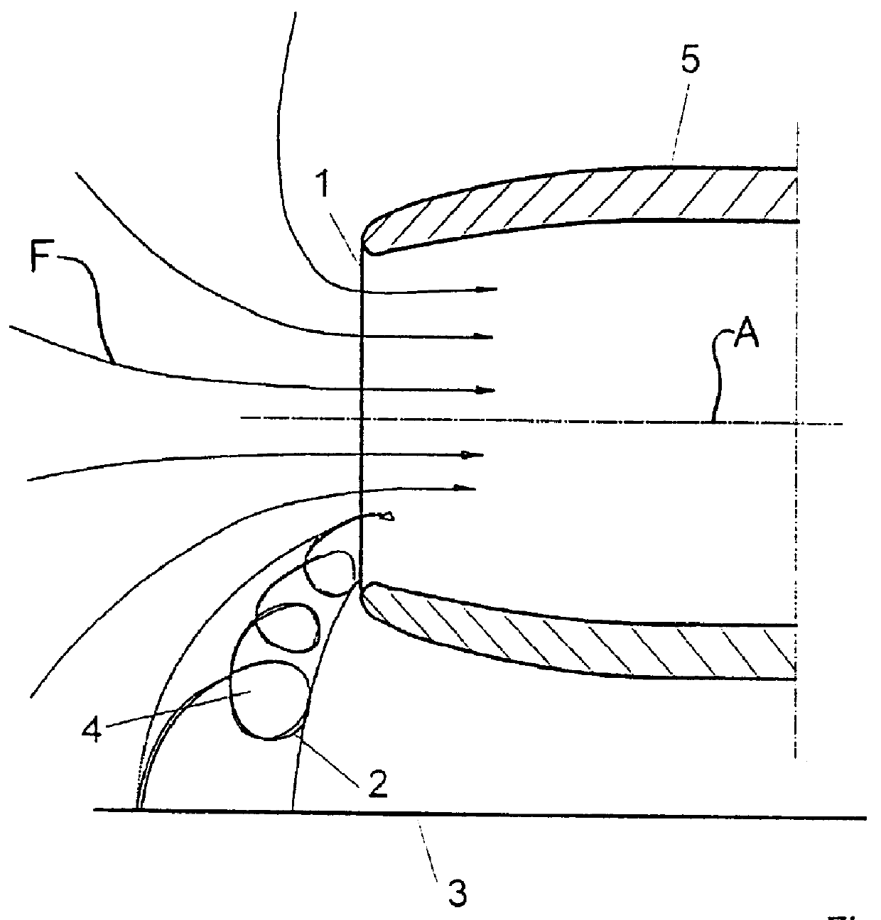
FIG. 1 shows a conventional arrangement of a turbine engine 5 near the non-air-permeable ground 3, whereby the ground effect results in the generation of a fully formed spiral vortex 2 having a vortex core 4, that is generated at or near the ground 3 and extends from the ground 3 into the air intake 1 of the engine 5. The problems associated with such vortex generation have been discussed above.

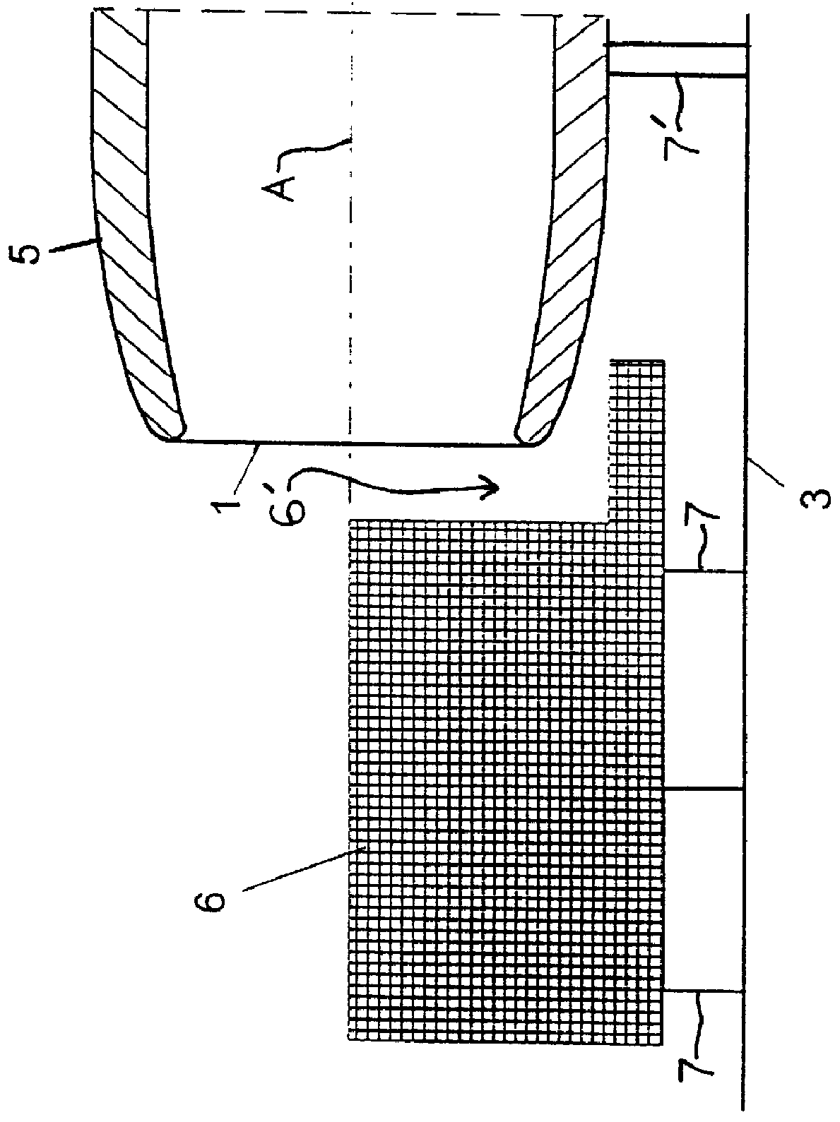
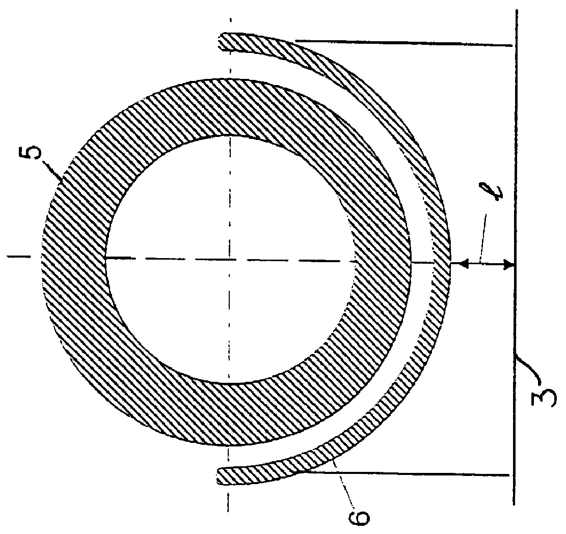
As shown in FIGS. 2A and 2B, the invention provides for an air permeable element 6 arranged between the ground 3 and the engine 5, extending axially in front of the air intake 1 of the engine 5, in such a manner so as to provide and ensure an inflow of air through the air permeable element 6 into the core 4 of any spiral vortex 2 being generated, as well as a sufficient after-flow of air for the duration of a static test of the engine 5. The engine 5 is supported relative to the ground 3 by any support elements 7' that may comprise any known test stand or the like.

The air permeable element 6 ...


PUM


Abstract

When a turbine engine is operated near the ground, for example on a stationary static test stand, the ground effect as well as excessive lateral wind effects can lead to instabilities and unacceptable flow conditions of the air flow entering the air intake of the engine. A method for stabilizing or preventing such instabilities in the engine intake air flow involves preventing the generation or full development of a spiral vortex extending between the ground and the engine air intake. Specifically, by positively introducing air into the vortex core of any spiral vortex being formed, the vortex is destroyed and full development of the vortex is prevented. An apparatus for carrying out the method includes an air permeable element arranged between the ground and the engine air intake, such that a flow of air is provided through the air permeable element into the core of any spiral vortex being formed on the surface of the air permeable element.

Description

PRIORITY CLAIMThis application is based on and claims the priority under 35 U.S.C. .sctn.119 of German Patent Application 197 43 591.2, filed on Oct. 2, 1997, the entire disclosure of which is incorporated herein by reference.The invention relates to a method and an apparatus for stabilizing an intake air flow of a ground-based turbine engine, such as a turbine engine mounted on a testing stand for carrying out a static test, wherein the ground effect as well as excessive lateral wind effects can lead to unacceptable air flow conditions that are to be prevented.BACKGROUND INFORMATIONDuring flight operation, a turbine engine of an aircraft can be represented with regard to a flow analysis, to a good approximation, as a point sink that sucks in air. In this context, it is possible to achieve a nearly constant flow velocity over the entire surface area of the intake cross-section by appropriately forming or configuring the intake contours. Such a constant axial flow velocity over the e...

Claims


Application Information

Patent Timeline
IPC IPC(8): B64F1/26B64F1/00F02C7/04
CPCB64F1/26F02C7/04Y10S415/914
Inventor GERHARDT, HANS-JOACHIMKRUEGER, OLIVERMEESSEN, HORSTESTADIEU, JEAN-B.
Owner DAIMLER CHRYSLER AEROSPACE AIRBUS
Why Eureka
Try Eureka