Helical-blade fluid machine

a fluid machine and helical blade technology, applied in machines/engines, liquid fuel engines, positive displacement liquid engines, etc., can solve the problems of increasing the weight and cost of the fluid machine, increasing the temperature of the lubricant, and decreasing the viscosity

Inactive Publication Date: 2000-12-19
KK TOSHIBA
View PDF5 Cites 18 Cited by
  • Summary
  • Abstract
  • Description
  • Claims
  • Application Information

AI Technical Summary

Benefits of technology

Another object of the present invention is to provide a helical-blade fluid machine having a casing that is thin and light.
Still another object of the present invention is to provide a helical-blade fluid machine having a roller that does not stir lubricant, thereby securing the stable operation of a compression mechanism.

Problems solved by technology

This dissolved much coolant in the lubricant under the high-pressure atmosphere, thereby increasing the temperature of the lubricant and decreasing the viscosity thereto to improperly lubricate the long bearings of the compression mechanism.
Namely, the casing must have a thick wall, which increases the weight as well as cost of the fluid machine.
When the roller of the compression mechanism in the lubricant pool is driven, it stirs the lubricant, to destabilize the supply of the lubricant, thereby destabilizing the torque and total operation of the compression mechanism.

Method used


Image

  • Helical-blade fluid machine
  • Helical-blade fluid machine
  • Helical-blade fluid machine

Examples


Embodiment Construction

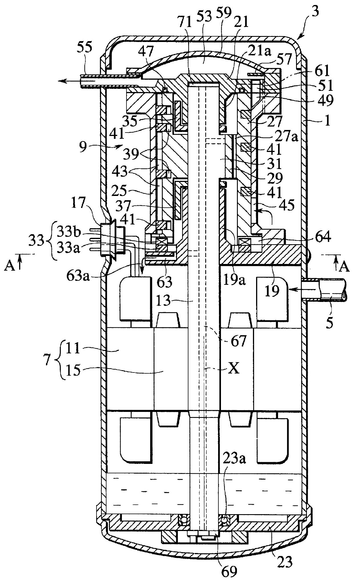
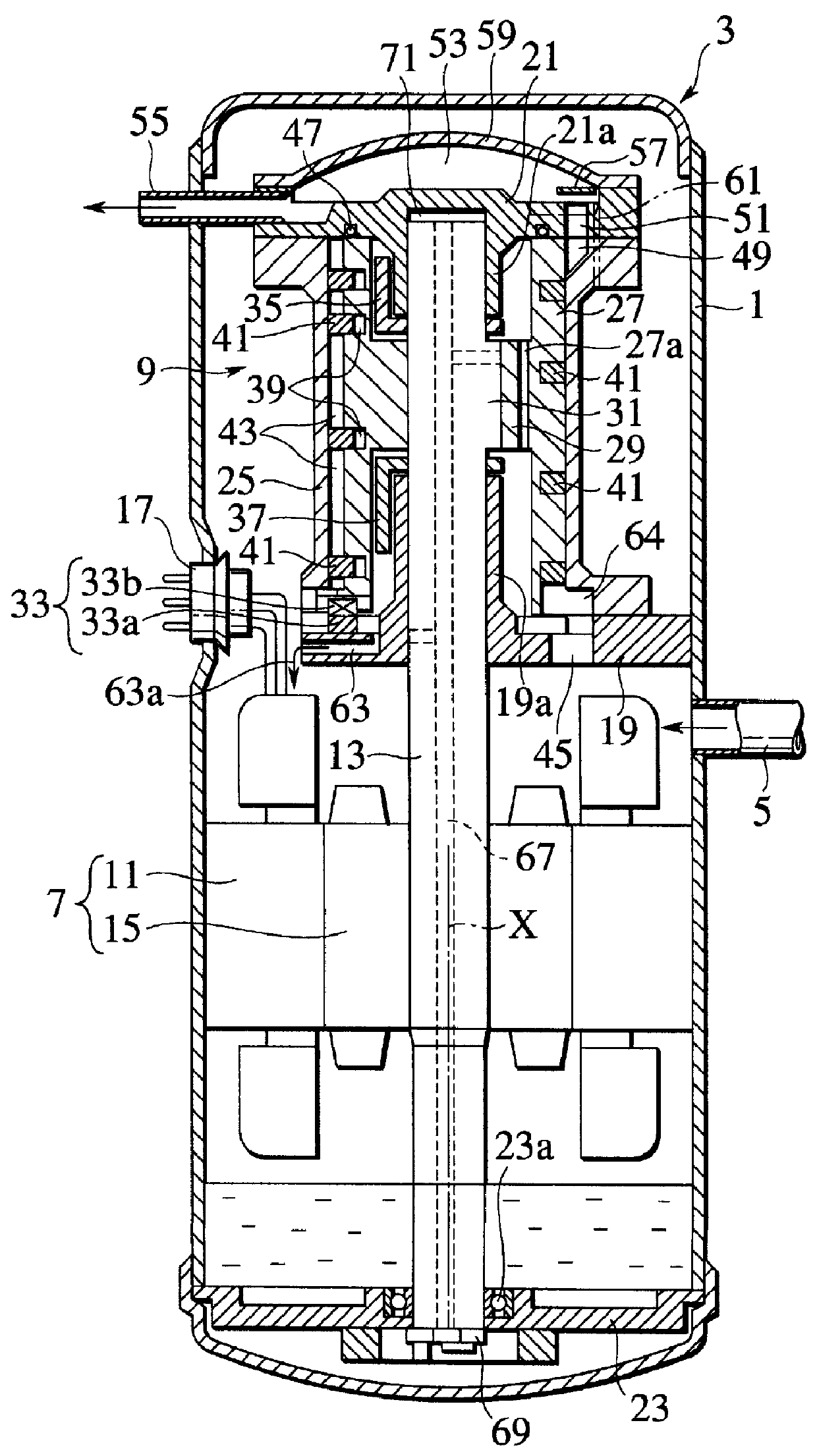
A helical-blade fluid machine according to an embodiment of the present invention will be explained with reference to FIGS. 1 and 2.

The fluid machine 3 is used in a refrigerating cycle and has a closed casing 1. The casing 1 has an intake pipe 5 and incorporates a drive mechanism 7 and a compression mechanism 9 that is arranged above the drive mechanism 7.

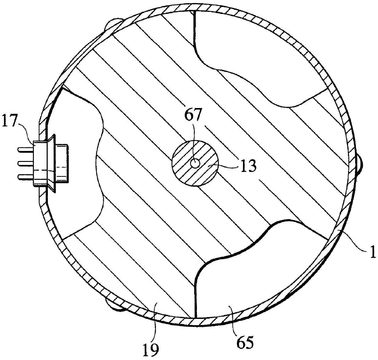
The drive mechanism 7 consists of a stator 11 fixed to the inner wall of the casing 1, and a rotor 15 fixed to a rotating shaft 13. The stator 11 is energized from a terminal fitting 17, to drive the rotor 15, which drives the shaft 13.

The shaft 13 also serves for the compression mechanism 9. The shaft 13 is rotatively supported at three positions. Namely, a first support frame 19 is fixed to the inner wall of the casing 1 and has a bearing 19a for supporting an intermediate part of the shaft 13. A second support frame 21 is fixed to the inner wall of the casing 1 and has a bearing 21a for supporting a top part of the shaft 13. A t...


PUM


Abstract

A helical-blade fluid machine maintains a low-pressure atmosphere in a closed casing (1) and secures a proper lubrication state for a compression mechanism (9). The fluid machine has a drive mechanism (7) that is installed at an upper or lower part of the casing and consists of a stator (11) and a rotor (15). The compression mechanism is installed at the other part of the casing. The compression mechanism has a cylinder (23) and a roller (25), which is swayed with respect to the cylinder by the drive mechanism. A helical blade (39) having unequal pitches is arranged on the roller, to define compression chambers (41). This arrangement lowers the head of lubricant. An intake pipe (5) feeds gas into the casing so that a low-pressure atmosphere fills the casing.

Description

1. Field of the InventionThe present invention relates to a helical-blade fluid machine applicable to compressors, expansion machines, pumps, etc.2. Description of the Prior ArtA helical-blade fluid machine has, in a closed casing, a cylinder and a roller piston eccentrically arranged in the cylinder. The peripheral surface of the roller piston has a helical groove in which a helical blade is inserted to define compression chambers in the cylinder. Relative motion between the cylinder and the roller piston draws coolant gas from an intake end of the cylinder into the compression chambers and successively conveys and compresses the gas toward a discharge end of the cylinder. The compressed gas fills the casing and is discharged outside.Generally, the helical-blade fluid machine directly draws gas into a compression mechanism, compresses the gas therein, once discharges the compressed gas into the casing, and sends the gas outside through a discharge pipe attached to the casing. As a ...

Claims


Application Information

Patent Timeline
Patent Type & Authority Patents(United States)
IPC IPC(8): F04C18/08F04C18/107F04C23/00
CPCF04C18/107F04C23/008F04C2240/603
Inventor HAYANO, MAKOTOSAKATA, HIROTSUGUMORISHIMA, AKIRAOZU, MASAO
Owner KK TOSHIBA
Why Eureka
Try Eureka