Gun having a rapid fire trigger assembly and the assembly therefor

a trigger assembly and rapid firing technology, applied in the field of weapons, can solve the problems of complicated devices, difficult installation and operation of guns, limited lifespan, etc., and achieve the effect of improving the ability to be fired quickly, easy installation and repair, and increasing the rapid firing capability

Inactive Publication Date: 2000-12-26
TRONCOSO VINCENT F
View PDF14 Cites 29 Cited by
  • Summary
  • Abstract
  • Description
  • Claims
  • Application Information

AI Technical Summary

Benefits of technology

The improved gun and trigger assembly of the present invention satisfy all the foregoing needs. Thus, the present invention is directed to a gun which has an improved capability of being fired rapidly and with total control, and to a novel trigger assembly which effects the desired increase in rapid firing capability. The asse

Problems solved by technology

Most such devices are complicated, expensive, difficult to install on a gun and to operate and have a limited lif

Method used


Image

  • Gun having a rapid fire trigger assembly and the assembly therefor
  • Gun having a rapid fire trigger assembly and the assembly therefor
  • Gun having a rapid fire trigger assembly and the assembly therefor

Examples


Embodiment Construction

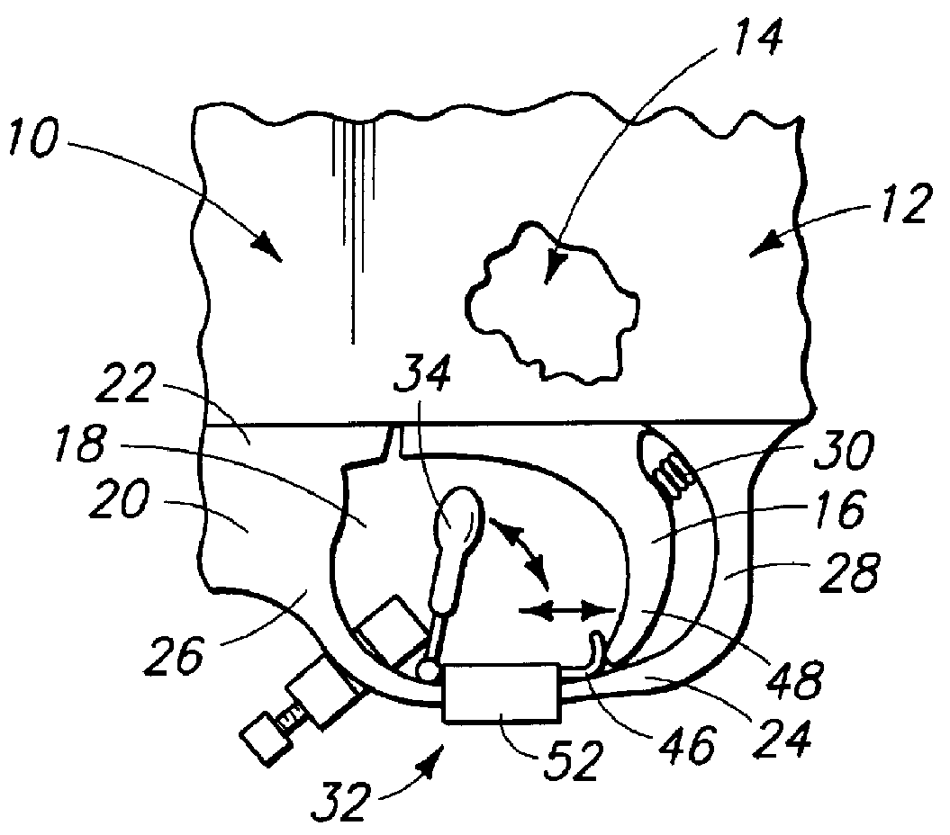
FIG. 1 is a schematic fragmentary side elevation, partly broken away, of a preferred embodiment of the improved gun and assembly of the present invention, showing the gun trigger in the spring-biased forward non-firing position;

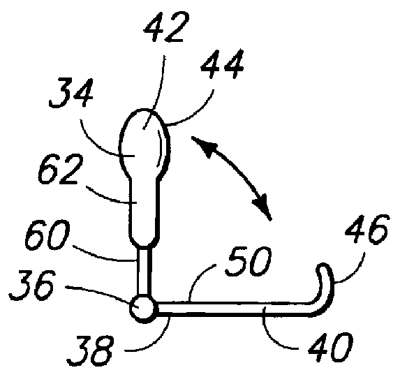
FIG. 2 is an enlarged schematic side elevation of the lever of the assembly and gun of FIG. 1, shown pivotably connected to the connector of the assembly and gun;

FIG. 3 is an enlarged schematic side elevation of the pivot block of the assembly and gun of FIG. 1;

FIG. 4 is an enlarged schematic front elevation of the pivot block of FIG. 3, shown clamped to the bar of the housing of the gun of FIG. 1;

FIG. 5 is an enlarged schematic transverse cross-section of the assembled retainer band, connector and housing bar of the gun of FIG. 1, viewed from the front thereof and showing the rear end of the connector rising above the retainer band; and,

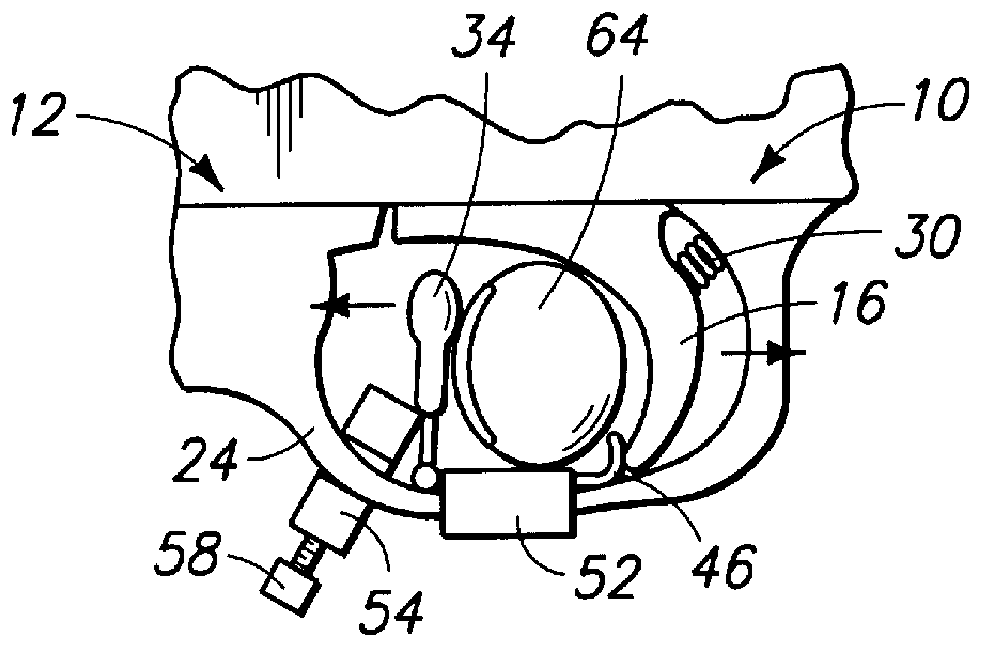
FIG. 6 is a schematic side elevation of the gun and assembly of FIG. 1, shown with a gunner's finger in place between the l...


PUM


Abstract

The gun of the present invention has a rapid fire trigger assembly. The gun includes a main body with a trigger rotatably secured therein for operating the firing mechanism of the gun. The trigger has a lower portion depending below the main body into a trigger housing or guard below the main body. The housing includes an upper portion connected to the underside of the main body of the gun and a lower horizontal bar spaced therebelow and defining therewith a finger space. The trigger is spring biased into a forward nonfiring position and is rotatable into a rear firing position. A detachable and adjustable rapid fire assembly is attached to the bar of the housing and includes a lever projecting up into the finger space in front of and spaced from the trigger, a connector with its front end pivotally secured to the lower end of the lever and a rear end adapted to contact the first trigger. The middle portion of the connector is rigidly secured to a retainer band slideably secured to the bar for movement between forward and rearward positions. An elongated pivot block is adjustably secured to the bar in front of the lever and projects up into the path of the lever, contacting the lower portion thereof so that when the lever is pivoted forwardly said connector rear end is driven rearwardly into the trigger to cause the trigger to fire the gun.

Description

1. Field of the InventionThe present invention generally relates to weapons and more particularly relates to an gun which has a rapid fire trigger assembly, and the rapid fire trigger assembly for said gun.2. Prior ArtVarious devices have been invented to increase the speed which a semi-automatic gun can be fired. Most such devices are complicated, expensive, difficult to install on a gun and to operate and have a limited lifespan. Moreover, most such devices are expensive and bulky and hard to repair and to adjust for optimal efficiency.Accordingly, it would be desireable to be able to provide a simple, inexpensive, durable device for installation on a semi-automatic gun which would increase appreciably the speed at which the gun could be conveniently fired. Such device should be easy to install and repair and, moreover, should be easy to adjust to customize the gun to the needs of the gunner utilizing such gun.SUMMARY OF THE PRESENT INVENTIONThe improved gun and trigger assembly o...

Claims


Application Information

Patent Timeline
IPC IPC(8): F41A19/00F41A19/16F41A19/09
CPCF41A19/16F41A19/09
Inventor TRONCOSO, VINCENT F.
Owner TRONCOSO VINCENT F
Why Eureka
Try Eureka