
Eureka
For R&D, Eureka makes reading and utilizing patents & technical documents easy.
Eureka AIR
Designed for self-driven R&D workflows. Generate viable solutions, solve complex R&D challenges, empower your innovation with AI.

Eureka Materials
Designed for material experts only. Revolutionize your material R&D, from search, analyze, to developing new materials.

TechResearch
Generate reliable direction feasibility study reports for your R&D in just a few steps.

TechSeek
Discover and master advanced knowledge NOW. Basics, ideas, possibilities, all at once.

TechMind
As an expert in R&D Theories, TechMind can generates customized viable solutions instantly.

TechRisk
Analyze your overall solution with one click, know your potential R&D risks in advance.

TechMonitor
Get weekly tech updates, stay abreast of the latest tech innovations and key insights.
Graphics processing method and apparatus thereof
- Summary
- Abstract
- Description
- Claims
- Application Information
AI Technical Summary
Benefits of technology
Problems solved by technology
Method used
Image

Examples
first embodiment
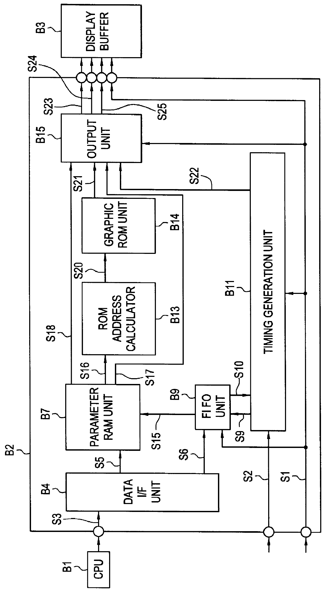
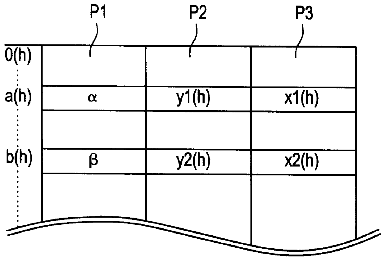
A first embodiment according to the present invention will be described in detail with reference to the flowchart of FIG. 7, the circuit configuration of FIG. 8, the data configuration of a parameter RAM unit shown in FIG. 9, and the data configuration of an updating register shown in FIG. 10. Note that explanations of elements already contained in the conventional circuit (shown in FIG. 2) are omitted.
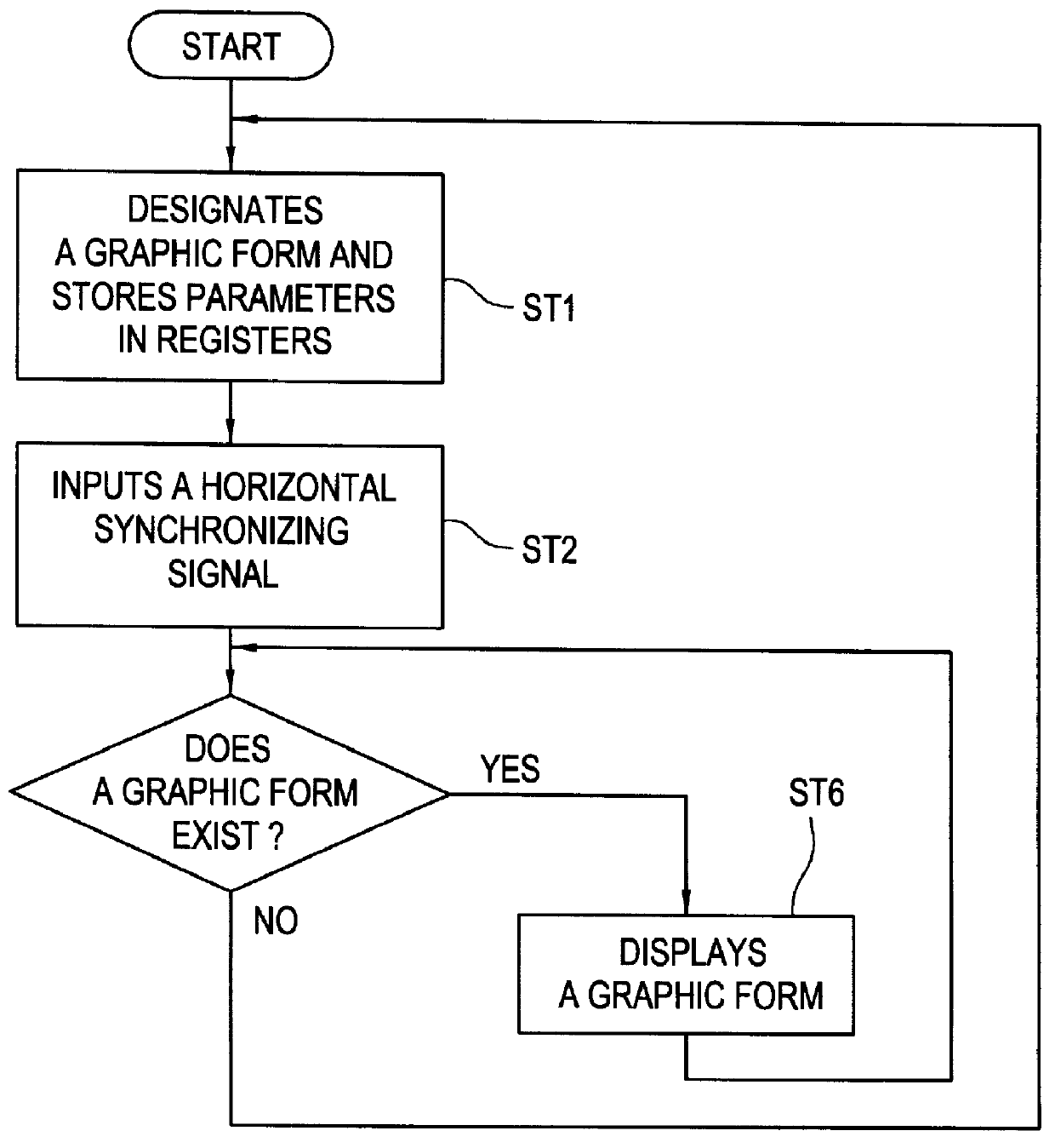
In the first embodiment, a graphic form will be displayed on a display by the following procedure as shown in FIG. 7. In step ST1, data and parameters for displaying a graphic form are sent to the graphics processing unit (B2 in FIG. 8). In step ST2, upon reception of a horizontal synchronizing signal S2, the graphics processing unit (B2 in FIG. 8) starts its operation. In step ST3, the timing generation unit B11 counts the number of received horizontal synchronizing signals S2. Until the number reaches a given value (a predetermined value), the timing generation unit B11 sends itself...
second embodiment
The second embodiment differs from the first embodiment in the updating register B5 and the address updating unit B16. The other units are the same as those in the first embodiment, and follow the procedure shown in FIG. 7.
The updating register B5 of the second embodiment is, as shown in FIG. 13, stored with both the logical ANDed and ORed values of a graphic ROM original address corresponding to a primitive graphic form, and a graphic ROM original address corresponding to a dynamic graphic form. As will be described later, with these ANDed and ORed values preset to respective predetermined values, the updating unit B16 makes an AND operation and OR operation between the ANDed value and the graphic ROM original address P1, and also between the ORed value and the original address P1. A specific part of the graphic ROM original address P1 is thereby changed into a given value. The resultant value is output as an updated graphic ROM original address signal S19 to the ROM address calcul...
third embodiment
In the second embodiment, graphic forms for dynamic images are designated by the ANDed value P6 and ORed value P7 stored in the updating register B5. The advantage of this approach will be made more apparent in the third embodiment. In the third embodiment, a WAIT control approach is different from that of the second embodiment. It should be noted, however, that the advantages of the address designation approach using the ANDed value P6 and ORed value P7 are nonetheless retained in the third embodiment.
The third embodiment will be detailed with reference to the flowchart in FIG. 16, the circuit configuration in FIG. 17 and FIG. 18, the data configuration of a parameter RAM unit in FIG. 19, and the data configuration of an updating register in FIG. 13. The explanations of elements already explained in the first and second embodiments are omitted.
In the third embodiment, additional parameters will be stored in the updated pointer RAM unit B8 so that the frame feeding time register B6 ...
PUM
 Abstract
Description
Claims
Application Information
 - R&D Engineer
- R&D Manager
- IP Professional
- Industry Leading Data Capabilities
- Powerful AI technology
- Patent DNA Extraction
Browse by: Latest US Patents, China's latest patents, Technical Efficacy Thesaurus, Application Domain, Technology Topic, Popular Technical Reports.
© 2024 PatSnap. All rights reserved.Legal|Privacy policy|Modern Slavery Act Transparency Statement|Sitemap|About US| Contact US: help@patsnap.com