Protective shield for electrical components

a technology for protecting shields and electrical components, applied in the direction of electrical apparatus construction details, coupling device connections, containers, etc., can solve the problems of complicated arrangement of components on circuit boards, interference with communications e.g. telecommunication, and the solution is not completely optimal

Inactive Publication Date: 2000-12-26
TELEFON AB LM ERICSSON (PUBL)
View PDF16 Cites 42 Cited by
  • Summary
  • Abstract
  • Description
  • Claims
  • Application Information

AI Technical Summary

Problems solved by technology

It is well known that radiation from certain components at high frequencies can cause interference with communications e.g. telecommunication.
The problem of the above contact springs is that they are quite complicated to arrange around the component on the circuit board.
This solution is, furthermore, not completely optimal, both with regard to space requirements and the degree of protection.
A problem which occurs when different products tend towards smaller and smaller dimensions is that the screening between sensitive components must be increased.
Another problem is that known protective shields take up too much room and are complicated and time-consuming to place on the circuit board, either because they should be mounted in holes in the circuit board or because they should be held fixed during the soldering operation.
The above mentioned problems often require hand assembly.

Method used


Image

  • Protective shield for electrical components
  • Protective shield for electrical components
  • Protective shield for electrical components

Examples


Embodiment Construction

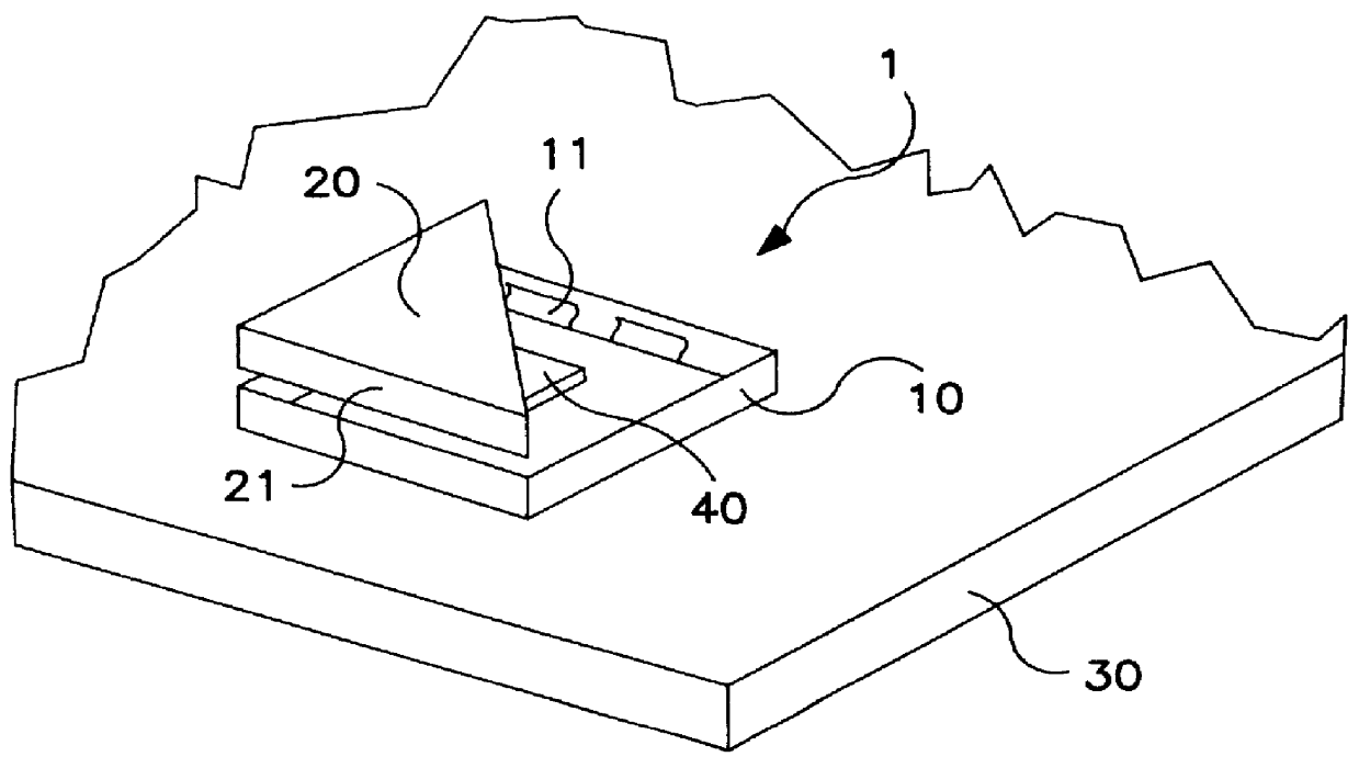
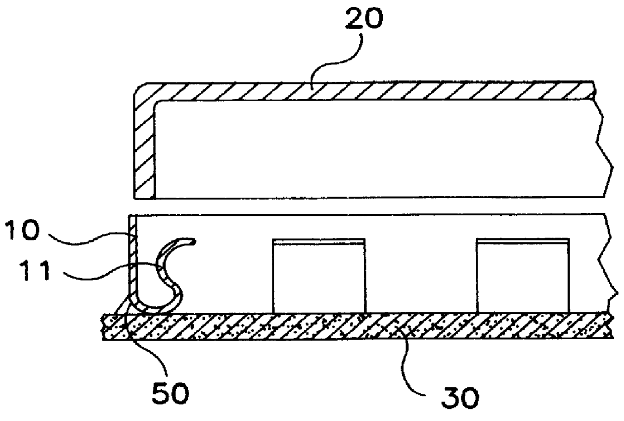
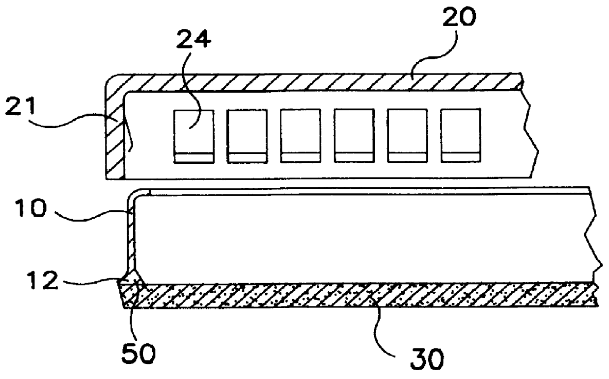
FIG. 1 shows an embodiment of a protective shield of the EMC-type 1 according to the invention. The protective shield 1 in this Figure is mounted on a substrate 30. The protective shield comprises a frame 10 and a lid 20. The frame 10 can be fastened to the substrate 30 with the help of gluing, welding or soldering. On the inside of the walls of the frame 10 there are a number of contact elements 11. These contact elements 11 in this embodiment are shaped as tension prongs. The outer dimensions of the lid 20 are adapted to the inner dimensions of the frame 10 according to FIG. 2. When the lid 20 is forced down into the frame 10, the side walls 21 of the lid 20 are gripped between the walls of the frame 10 and the tension prongs. The component 40, which one desires to shield, is placed inside the frame 10. Said tension prongs can also be arranged on the outside of the frame 10. The inner dimensions of the lid 20 are in this case adapted to the shape and size of the outer dimensions o...


PUM


Abstract

The present invention relates to a protective shield (1) of EMC-type, for e.g. electrical components (40) on a circuit board (30). The protective shield (1) comprises a frame (10) with associated lid (20), where said frame (10) at the end facing towards the circuit board (30) comprises a flange (12). The frame is arranged to be fastened to the circuit board (30) by means of gluing, welding or soldering. The frame (10) is intended to surround at least one component (40) so that electrical contact is formed between said circuit board (30) and said frame (10) and between said frame (10) and said lid (20).

Description

The present invention relates to a surface-mounted protective shield for components on e.g. a circuit board.STATE OF THE ARTThe screening of components on circuit boards is becoming more important, especially in the case when the signal speed approaches the Gbit region. It is well known that radiation from certain components at high frequencies can cause interference with communications e.g. telecommunication. This phenomenon is called RFI, radio frequency interference. The interfering circuits can either be shielded with closed boxes or the sensitive components can be shielded with closed boxes in order to prevent interference.In GB 2 226 187 there is described a miniature protective shield for electronic components arranged on a circuit board. The protective shield comprises a number of contact springs and a lid. The contact springs are arranged around the component and are in electrical contact with the circuit board. The contact springs are in general U-shaped. The lid comprises...

Claims


Application Information

Patent Timeline
Patent Type & Authority Patents(United States)
IPC IPC(8): H05K9/00
CPCH05K9/0032H05K9/00
Inventor OLOFSSON, LARS-ANDERSBJORKSELL, SVEN-ERIK
Owner TELEFON AB LM ERICSSON (PUBL)
Why Eureka
Try Eureka