Push-pull power converter circuit

Inactive Publication Date: 2000-12-26
OPTIS WIRELESS TECH LLC
View PDF3 Cites 19 Cited by
  • Summary
  • Abstract
  • Description
  • Claims
  • Application Information

AI Technical Summary

Problems solved by technology

However, the devices usually receive power from a single or limited number of power sources (e.

Method used


Image

  • Push-pull power converter circuit
  • Push-pull power converter circuit
  • Push-pull power converter circuit

Examples


Embodiment Construction

The numerous innovative teachings of the present application will be described with particular reference to the presently preferred exemplary embodiments. However, it should be understood that this class of embodiments provides only a few examples of the many advantageous uses of the innovative teachings herein. In general, statements made in the specification of the present application do not necessarily delimit any of the various claimed inventions. Moreover, some statements may apply to some inventive features but not to others.

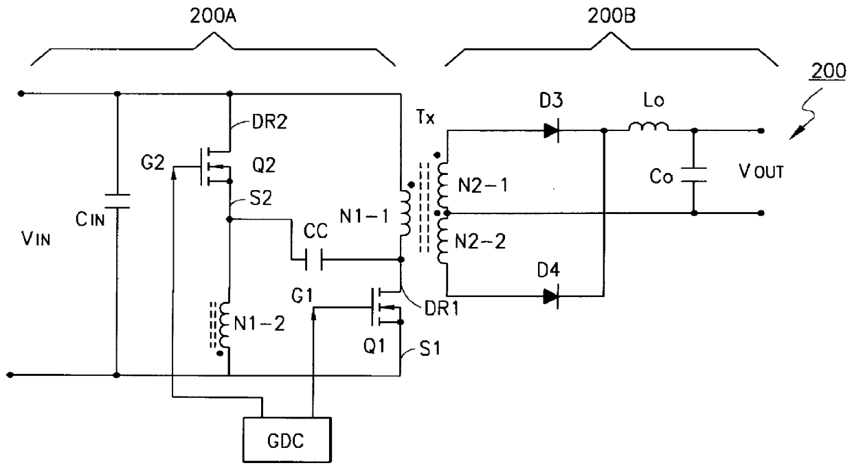
Referring now to FIG. 2, there is illustrated a diagram of a push-pull converter, designated generally by the reference numeral 200, embodying the present invention. The push-pull converter 200 includes a primary circuit 200A and an output section 200B. The primary circuit 200A includes an input terminal VIN connectable to an input voltage. An input capacitor CIN is placed across the input terminal VIN to filter the input. Additionally the push-pull conver...


PUM


Abstract

A push-pull converter for converting an input voltage to a selectable output voltage is disclosed. The push-pull converter includes a pair of primary switches and a pair of primary windings of a transformer. The voltage stress across the primary switches is regulated by means of a clamp capacitor. The clamp capacitor clamps the voltage of the primary switches during the reset of the primary windings of the transformer. An alternate embodiment is also disclosed in which the voltage stress across the primary switches is regulated by means of two clamp capacitors. The clamp capacitor clamps the voltage of the primary switches during the reset of the primary windings of the transformer. The clamp capacitors extend the transformer reset period to include the lagging dead time for the corresponding switches, as well as the complementary powering stage. Current in the output section during the dead times is permitted by means of an additional diode, therein.

Description

BACKGROUND OF THE PRESENT INVENTION1. Field of the InventionThe present invention relates to electronics, and more particularly to power supply systems.2. Description of Related ArtDigital electronic devices often require a number of direct current voltage (DC Voltage) for proper operation. However, the devices usually receive power from a single or limited number of power sources (e.g., a power outlet or battery) which do not necessarily correspond to the required DC voltages.Accordingly, a converter circuit is placed between the electronic device and the power source which receives an input DC voltage and produces a selectable DC voltage output. One type of converter is known as a switch mode power supply. Switch mode power supplies are characterized by the use of a high frequency switch with a varying duty cycle to maintain the output voltage.A popular type of switch mode power supply is known as a Push-Pull converter. Referring now to FIG. 1, there is illustrated a diagram of Pu...

Claims


Application Information

Patent Timeline
IPC IPC(8): H02M3/337H02M3/24
CPCH02M3/337H02M3/01
Inventor FARRINGTON, RICHARD W.HART, WILLIAM
Owner OPTIS WIRELESS TECH LLC
Why Eureka
Try Eureka