Imaging apparatus, image display apparatus and image recording and/or reproducing apparatus

a technology for displaying apparatus and imaging apparatus, which is applied in the field of imaging apparatus for displaying stereoscopic images, and can solve problems such as inability to fully reproduce practical stereoscopic feeling, large apparatus, and slow adjustment speed in comparison

Inactive Publication Date: 2001-01-23
OLYMPUS OPTICAL CO LTD
View PDF21 Cites 118 Cited by
  • Summary
  • Abstract
  • Description
  • Claims
  • Application Information

AI Technical Summary

Problems solved by technology

Particularly, the stereoscopic imaging apparatus disclosed in Japanese Patent Application Publication No. 39,836/92 has to use image processing television camera and the monitor for displaying its image in addition to two video cameras, so that a problem that whole apparatus becomes large arises.
Moreover, the adjusting speed becomes slow in comparison with the adjusting speed of focussing and smoothing of the imaging optical system.
However, the stereoscopic feeling felt by human under natural conditions can be obtained with following three functions, i.e. binocular parallax, binocular vergence and adjusting function, interactively, but in conventional stereoscopic imaging apparatus including the above examples, only the

Method used


Image

  • Imaging apparatus, image display apparatus and image recording and/or reproducing apparatus
  • Imaging apparatus, image display apparatus and image recording and/or reproducing apparatus
  • Imaging apparatus, image display apparatus and image recording and/or reproducing apparatus

Examples


first embodiment

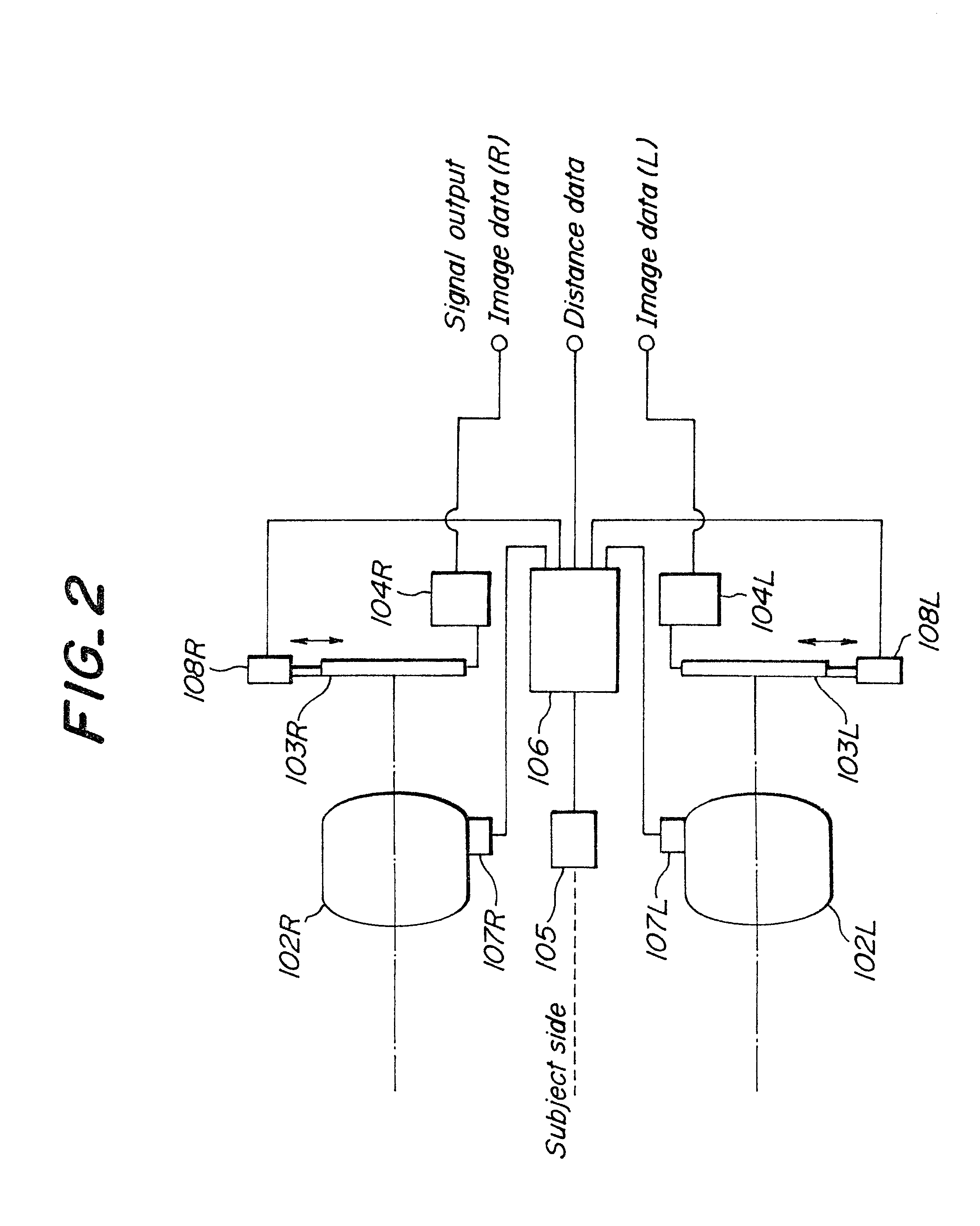
FIG. 2 shows an imaging section of the stereoscopic imaging apparatus as a In this embodiment, the apparatus is provided at a side of an object to be imaged, or viewed, with right and left imaging lens systems 102L, 102R (R is right side and L is left side) in such a manner that optical axes of these lens systems are substantially parallel, so as to focus these imaging lens systems 102L, 102R at required object positions by corresponding focus adjusting sections, respectively. Imaging elements 103L, 103R are provided behind the imaging lens systems 102L, 102R changeably in right and left direction orthogonal to optical axes of the imaging lens system corresponding to respective imaging element drive sections 108L, 108R, and outputs of these imaging elements 103L, 103R are supplied to respective imaging processing circuits 104L, 104R to obtain right video image data and left image data. A range sensor 105 is provided between imaging lens systems 102L, 102R so as to measure a distanc...

second embodiment

According to this embodiment, the imaging condition of the stereoscopic image can be set simply at the imaging in the same manner as in the second embodiment and as right and left image data, image data including equal information amount in the direction of basic line length about target subject can be obtained, and thus the smooth exhibiting condition can be ensured. Therefore, physical disorder feeling on the viewing of the stereoscopic image can be decreased, thereby obtaining a stable fusing.

The change of the basic line length according to this embodiment may also be applied to the above first embodiment.

fourth embodiment

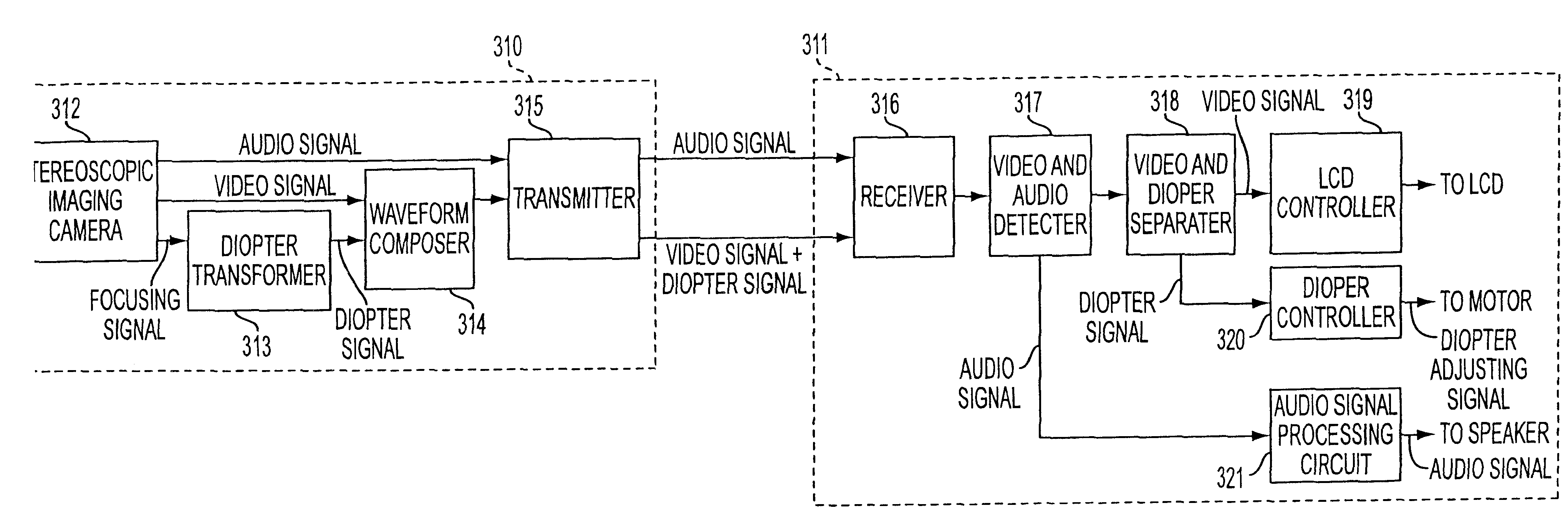
FIG. 8 shows a displaying section of the stereoscopic image display apparatus according to the present invention as a In this embodiment, the apparatus comprises display lens systems 203L, 203R disposed at the side of right and left eyes 202L, 202R, respectively, and display elements 204L, 204R disposed behind the display lens systems 203L, 203R. The display lens systems 203L, 203R are constructed by only ocular lens system or a combination of a ocular lens system and a relay lens system, in such a manner that right and left optical axes are disposed in parallel. The display elements 204L, 204R are held movably in the right and left directions orthogonal to the respective optical axes. In this case, the display elements 204L, 204R are constructed mainly by LCD, and are also made by two dimensional array of LCD or small LCD. Illuminating light sources 205L, 205R are disposed behind the display elements 204L, 204R.

The display elements 204L, 204R and the illuminating light sources 205...


PUM


Abstract

A stereoscopic image display apparatus having right and left display elements for displaying inputted stereoscopic image signals, right and left displaying optical systems for leading images displayed on the right and left image elements, a setting information element for outputting setting information signals on stereoscopic image display, based on the stereoscopic vision information signals about the inputted imaging distance in synchronization with the stereoscopic image signals, and a control element for controlling image position displayed on the right and left image display elements to at least optical axes of the right and left display optical systems, based on the setting information signals.

Description

1. Field of the InventionThe present invention relates to an apparatus for imaging a stereoscopic image, and an apparatus for displaying the stereoscopic image, more particularly, a head-mounted apparatus for displaying a stereoscopic image capable of viewing a stereoscopic image by leading different images on right and left eyes of a viewer.The present invention also relates to a stereoscopic image recording and / or reproducing apparatus.2. Related Art StatementIt is well known that a reception of stereoscopic information in binocular stereoscopic vision is dominant by means of binocular parallax. (See, For example, "Magazine of Television Society, Vol. 41, No. 7, PP. 604.about.609, 1987"). The stereoscopic feeling obtained by the binocular stereoscopic vision has an effect when an object is present in a distance of about 1 m.about.100 m, but the stereoscopic feeling obtained by a vergence angle has an effect when the object is present in a distance of 1 m.about.10 m.Hitherto, as a ...

Claims


Application Information

Patent Timeline
IPC IPC(8): G02B27/01H04N13/00H04N5/77H04N5/74H04N5/7824H04N5/92H04N5/7826G02B27/00H04N13/239
CPCG02B27/017G02B27/0172H04N5/7441H04N5/7491H04N5/77H04N13/0055H04N13/0239H04N13/025H04N13/0296H04N13/044H04N13/0497G02B2027/0132G02B2027/0178H04N5/78263H04N5/9201H04N5/9205H04N13/0003H04N13/0025H04N13/0048H04N13/0051H04N13/0059H04N13/0246H04N13/0289H04N13/0493H04N2005/745H04N2013/0077H04N2013/0081H04N2013/0096H04N13/289H04N13/167H04N13/344H04N13/194H04N13/189H04N13/246H04N13/393H04N13/161H04N13/296H04N13/10H04N13/239H04N13/25H04N13/398H04N13/133
Inventor TABATA, SEIICHIROSHIMADA, NAOTOIMAI, SATOSHIOKAMURA, TOSHIROTOGINO, TAKAYOSHIIBA, YOICHI
Owner OLYMPUS OPTICAL CO LTD
Why Eureka
Try Eureka