Apparatus and method for sealing fluid filter by infrared heating

Inactive Publication Date: 2001-01-30
USF FILTRATION & SEPARATIONS GROUP
View PDF26 Cites 28 Cited by
  • Summary
  • Abstract
  • Description
  • Claims
  • Application Information

AI Technical Summary

Problems solved by technology

A distinct disadvantage of the aforementioned process was that the bonding of both the first and second cylindrical ends of the filter media required two separate

Method used


Image

  • Apparatus and method for sealing fluid filter by infrared heating
  • Apparatus and method for sealing fluid filter by infrared heating
  • Apparatus and method for sealing fluid filter by infrared heating

Examples


Embodiment Construction

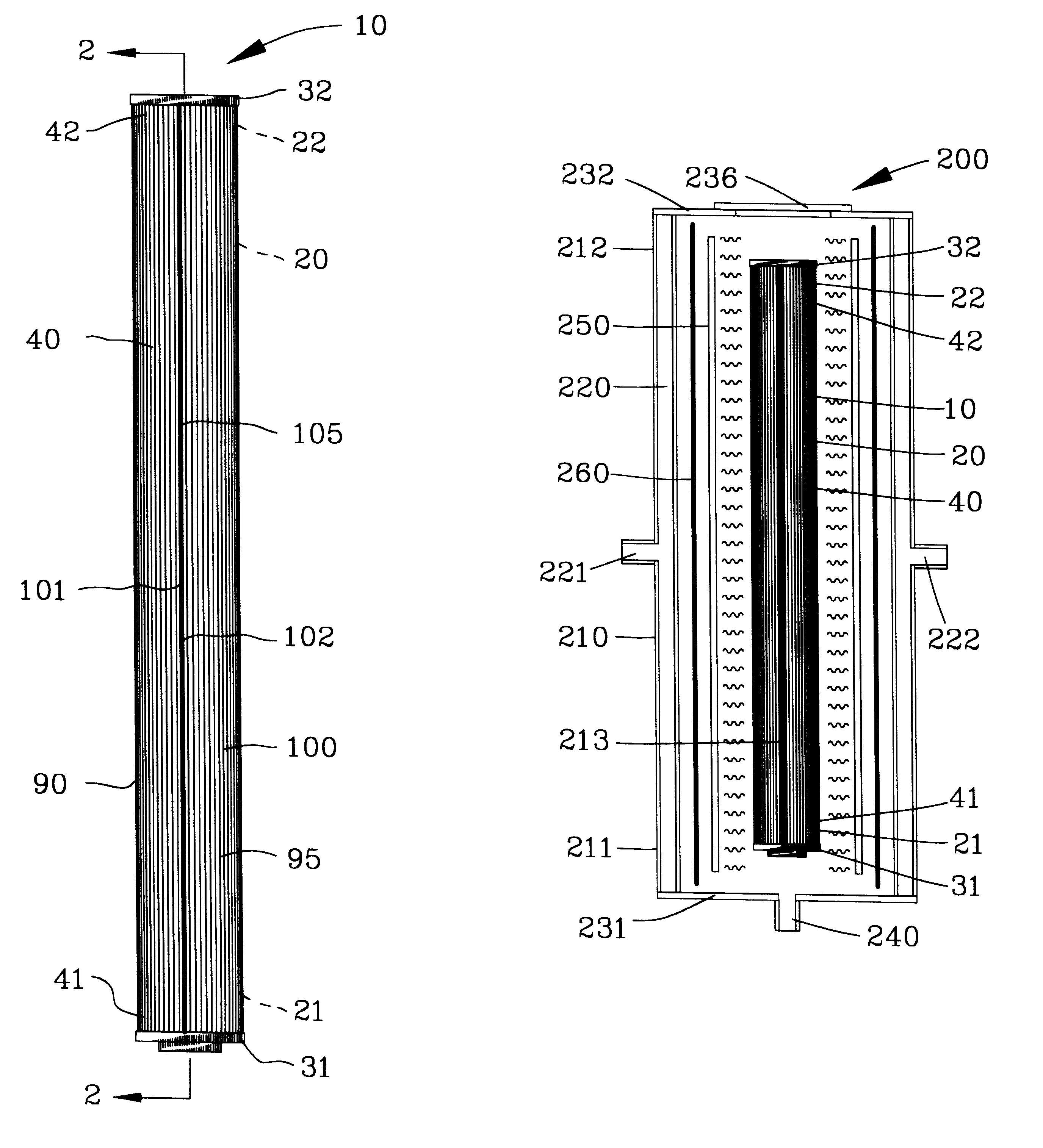
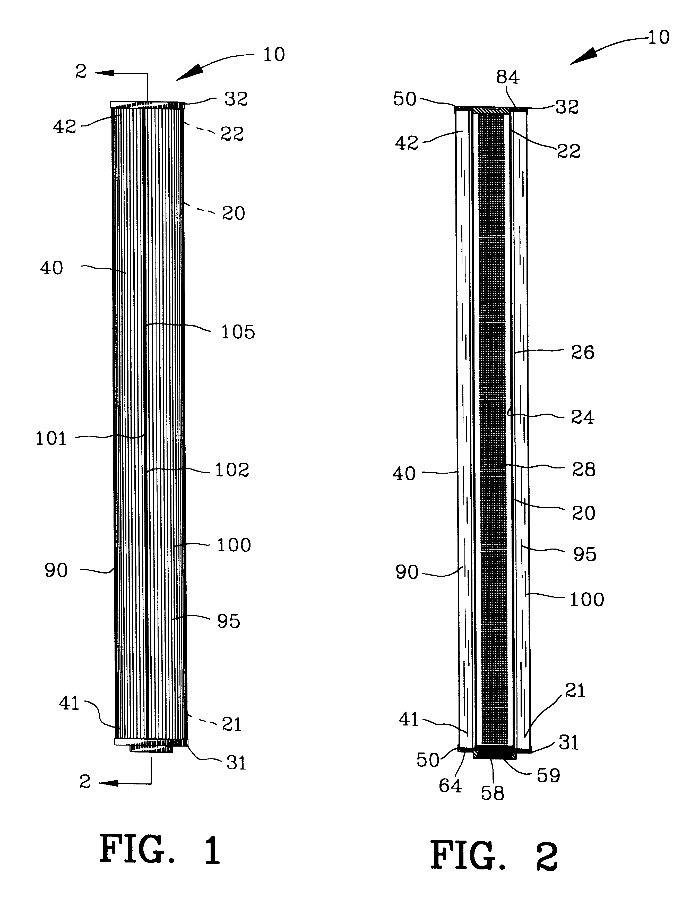
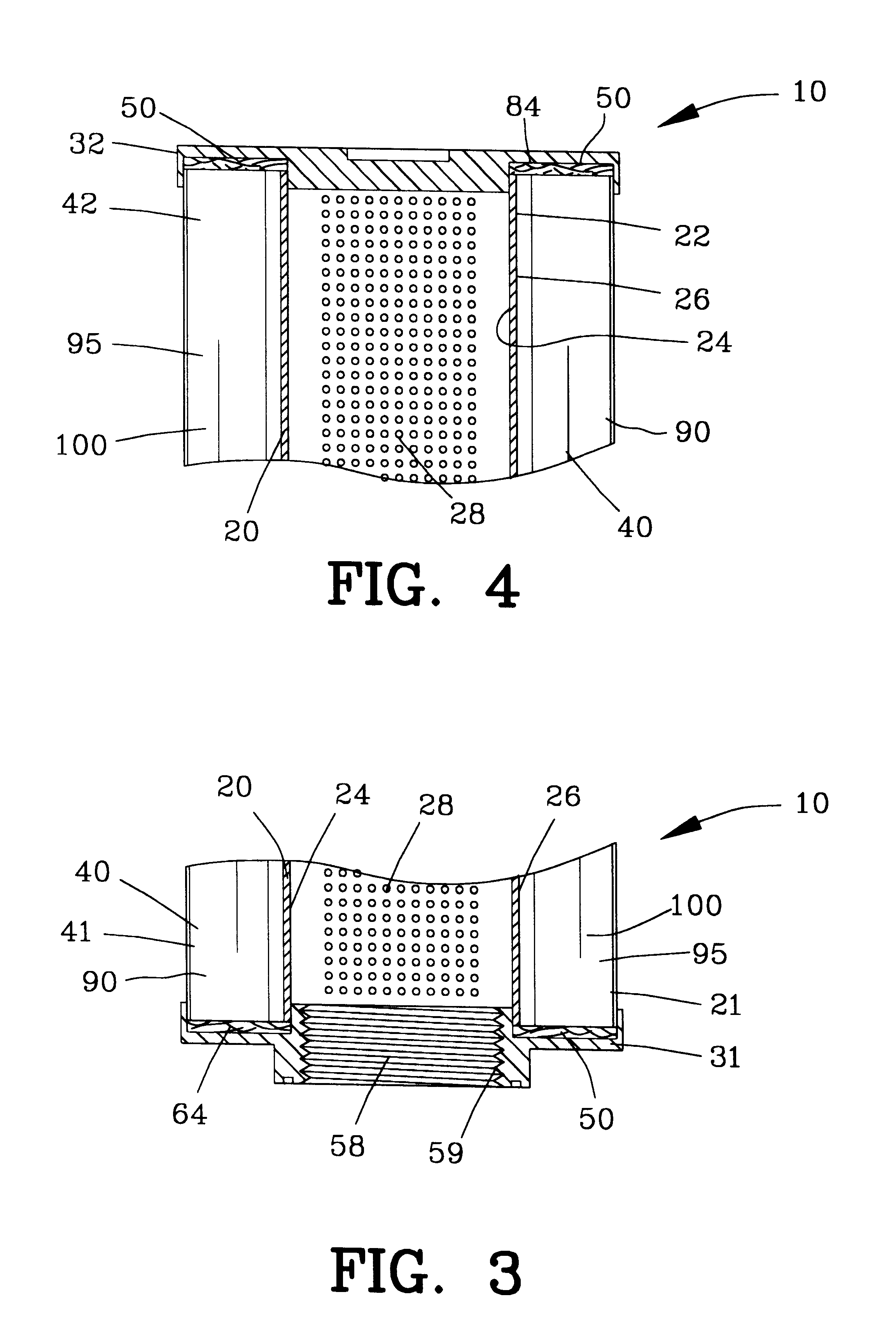
FIG. 1 is a side elevational view of the fluid filter insert 10 with FIG. 2 being a sectional view thereof. The fluid filter insert 10 is designed for use within a conventional filter housing (not shown) for filtering suspended contaminants from a fluid. The fluid filter insert 10 comprises a core member 20 extending between a first and a second core end 21 and 22 with the core member 20 being substantially cylindrically defined by an inner and outer cylindrical surface 24 and 26. A plurality of apertures 28 defined within the core member 20 to extend between the inner and outer cylindrical surfaces 24 and 26 for enabling fluid passage therethrough. The core member 20 is disposed between a first and a second support member 31 and 32.

The fluid filter insert 10 comprises a filter media 40 having a first and a second filter media end 41 and 42. The first and second core ends 21 and 22 of the core member 20 and the first and second filter media ends 41 and 42 of the filter media 40 are ...


PUM

PropertyMeasurementUnit
Diameteraaaaaaaaaa
Metallic bondaaaaaaaaaa
Wavelengthaaaaaaaaaa

Abstract

An apparatus and method is disclosed for sealing a filter element to a support member. An array of bonding fibers is interposed between the filter element and the support member. Infrared energy is applied for a period of time sufficient to at least partially melt the array of bonding fibers to sinter bond the filter element to the support member.

Description

1. Field of the InventionThis invention relates to the filtering of a fluid and more particularly to an apparatus and method for sealing a filter element to a support member by infrared energy.2. Background of the InventionIn a typical fluid filter, a porous filter media is secured to a support member or the like for mounting or suspending the filter media. In the case of a cylindrical filter, the filter media is formed into a cylindrical configuration and a first and a second cylindrical end of the filter media is bonded to a first and a second support member such as a first and a second end cap. The first and second end caps mount the filter media relative to a fluid input source and a fluid output source. In many cases, a braze material is used for affixing the first and second cylindrical ends of the filter media to the first and second end caps.In one example of the construction of the fluid filter, the first end cap was placed on the horizontal surface facing upwardly and fill...

Claims


Application Information

Patent Timeline
IPC IPC(8): B01D46/24B01D29/11
CPCB01D29/111B01D46/2411B01D29/21B01D2271/025Y10S55/05
Inventor QUICK, NATHANIEL R.LI, TAOMALANGA, ROBERTSIKKA, VINOD K.BLUE, CRAIG A.
Owner USF FILTRATION & SEPARATIONS GROUP
Why Eureka
Try Eureka