Pressure-dependent valve for a vibration damper

a technology of pressure-dependent valves and dampers, which is applied in the direction of shock absorbers, functional valve types, transportation and packaging, etc., can solve the problems of holding forces, which counteract the operating forces of the valve, and cannot be absorbed,

Inactive Publication Date: 2001-02-06
ZF FRIEDRICHSHAFEN AG
View PDF7 Cites 17 Cited by
  • Summary
  • Abstract
  • Description
  • Claims
  • Application Information

AI Technical Summary

Problems solved by technology

It is disadvantageous in that the prior art uses cup springs which are subject to significant fluctuations with respect to their spring force.
However, this is not possible with the prior art valves shown by the reference DE 44 01 393 C1.
Secondly, holding forces, which counteract operating forces in the valve, m...

Method used


Image

  • Pressure-dependent valve for a vibration damper
  • Pressure-dependent valve for a vibration damper
  • Pressure-dependent valve for a vibration damper

Examples


Embodiment Construction

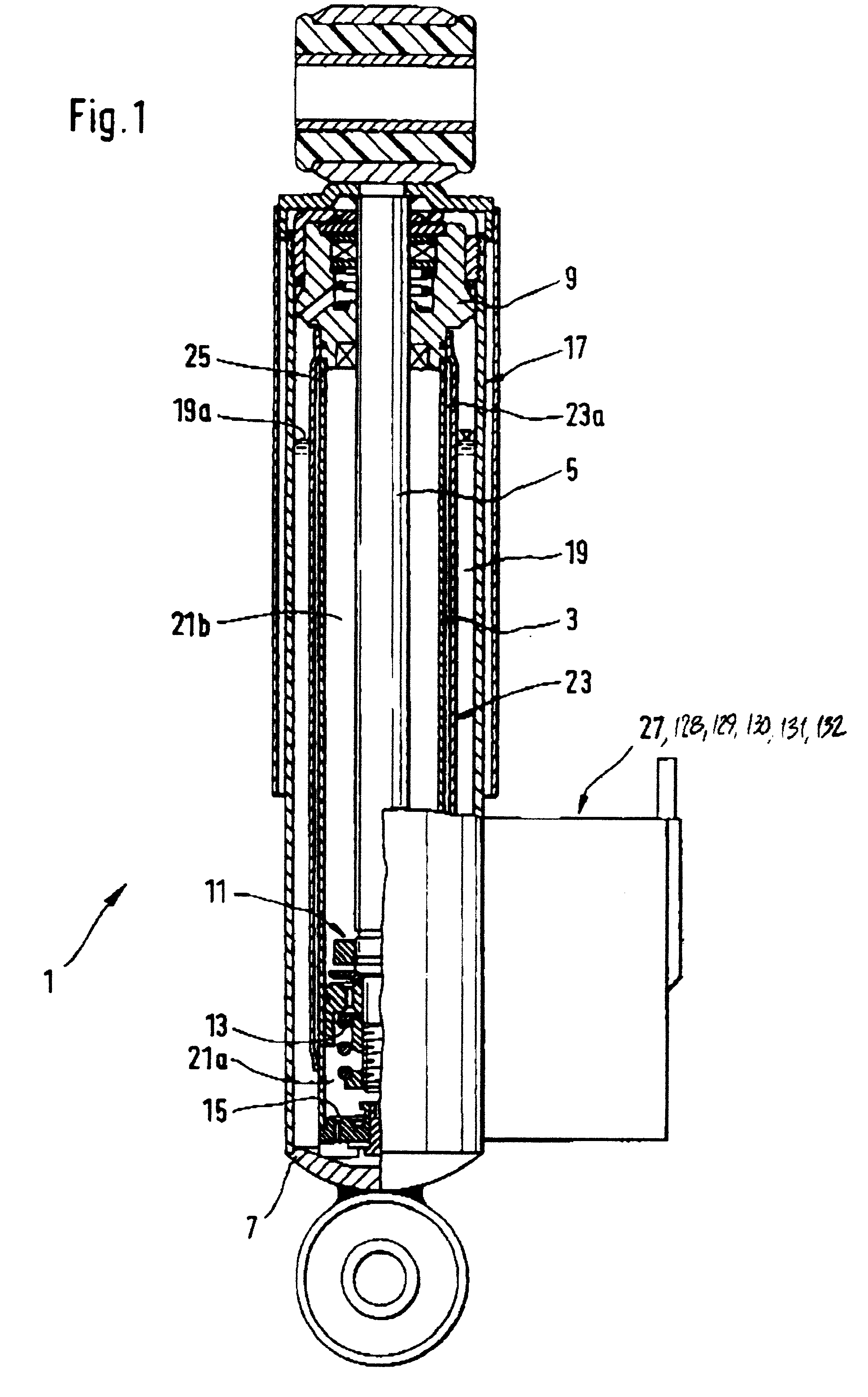
FIG. 1 shows a vibration damper 1 according to an embodiment of the invention with a cylinder 3 and a piston rod 5 axially movably arranged therein. The bottom end of the cylinder 3 is closed by a bottom 7. The piston rod 5 extends out from the upper end of the cylinder 3 through a guide and sealing unit 9. A piston unit 11 with a piston valve arrangement 13 is attached to the piston rod 5 inside the cylinder 3. The bottom 7 of the cylinder 3 is equipped with a bottom valve arrangement 15. The cylinder 3 is surrounded by a container tube 17. A compensation chamber 19 comprises an annular space between the container tube 17 and the cylinder 1. The space inside the cylinder 3 is divided by the piston unit 11 into a first working chamber 21a and a second working chamber 21b. The working chambers 21a and 21b are filled with a pressure fluid. The compensation chamber 19 is filled with fluid to level 19a with gas above that. An intermediate tube 23 inside the compensation chamber 19 defin...


PUM


Abstract

A pressure-dependent valve, for use with an adjustable vibration damper comprising a piston rod arranged in an axially movable fashion in a cylindrical tube filled with damping fluid, is controlled by a pressure transducer pressurized via a pressure connection opening. The pressure-dependent valve includes a valve body axially movable relative to a valve surface. The valve body and valve surface together determine a valve passage cross-section. The pressure transducer is float-mounted in a pressure space and supported by at least one spring. One of the valve parts determining the valve passage cross-section is movable relative to the current position of the pressure transducer by an adjustment device.

Description

1. Field of the InventionThe invention relates to a pressure-dependent valve for use with a vibration damper having a piston rod axially movably arranged in a fluid-filled cylindrical tube, the pressure-dependent valve being activated by an adjustment device that is pressurized via a pressure connection opening.2. Description of the Related ArtA prior art pressure-dependent valve for an adjustable vibration damper is disclosed in German reference DE 44 01 393 C1. The adjustable vibration damper includes a piston rod axially movably mounted in a cylindrical tube filled with damping fluid. The cylindrical tube has a connection to the pressure-dependent valve, which is activated by a pressurized adjustment device. The adjustment device has an axially movable valve body that is activated by a pressure transducer, which is float-mounted in a pressure space and supported by at least one spring. The spring that prestresses the pressure transducer determines the steepness of an opening forc...

Claims


Application Information

Patent Timeline
IPC IPC(8): F16F9/512F16F9/50
CPCF16F9/512Y10T137/7779
Inventor FORSTER, ANDREASKUHNEL, JOACHIM
Owner ZF FRIEDRICHSHAFEN AG
Why Eureka
Try Eureka